Assembly, Switch box wiring – Tiger Products Co., Ltd CNH T6010-80 User Manual
Page 41
ASSEMBLY
Assembly Section 2-9
SWITCH BOX WIRING
Refer to the Parts Section for wiring diagrams. Remove top instrument panel (tach, and
hour meter) for access to the wires.
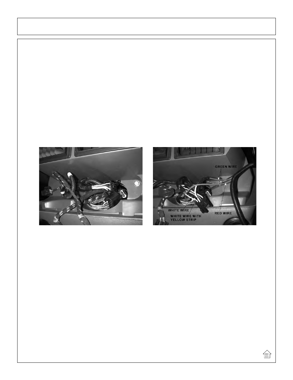
Route the red and green switch box wires from the switch box to the bottom right corner
of the instrument panel near window. Connect the red wire to the white wire. (hot when
key is in the ‘on’ position)
NOTE ONLY FOR ELECTRONIC VALVE: +12 VOLTS ELECTRICAL POWER
MUST BE TAKEN FROM A SOURCE LOCATION WHERE IT IS LIVE ONLY
WHEN THE IGNITION SWITCH IS IN THE “ON” POSITION. THIS WIRE MUST
BE FUSED A THE SOURCE LOCATION.
Route the white wire to the hydraulic solenoid brake valve.
The switch box is to be secured to the operators side of the control handles, or corner
switch box mount.
The green wires will connnect to the neutral safety switch wires (white with yellow
stripe), under the cowl panel.
(ASM-NH-0061)
BEFORE WIRING
AFTER WIRING