Temco dv5200 series – Temco Tool DV5200MB User Manual
Page 8
8
Temco DV5200 Series
78674
Materials such as cultured marble or other synthetic
materials are not recommended as they may discolor,
warp or create odor as a result of exposure to the tem-
peratures of the front of the fireplace.
Gas Specifications
Max.
Min.
Gas
Input
Input
Model
Fuel
Control BTU/h
BTU/h
DV5200MBN Natural
Hi/Lo
25,000
17,000
DV5200MBP Propane
Hi/Lo
25,000
17,500
Gas Line Installation
This gas appliance should be installed by a qualified in-
staller in accordance with local building codes and with
current CSA-B149.1 installation codes for Gas Burning
Appliances and Equipment in Canada and the National
Fuel Gas Code ANSI Z223.1/NFPA 54 in the U.S.A.*
1. The gas pipeline can be brought in through the bot-
tom or the right or the left side of the appliance. A
hole is provided at all locations to allow for the gas
pipe installation and testing of any gas connection.
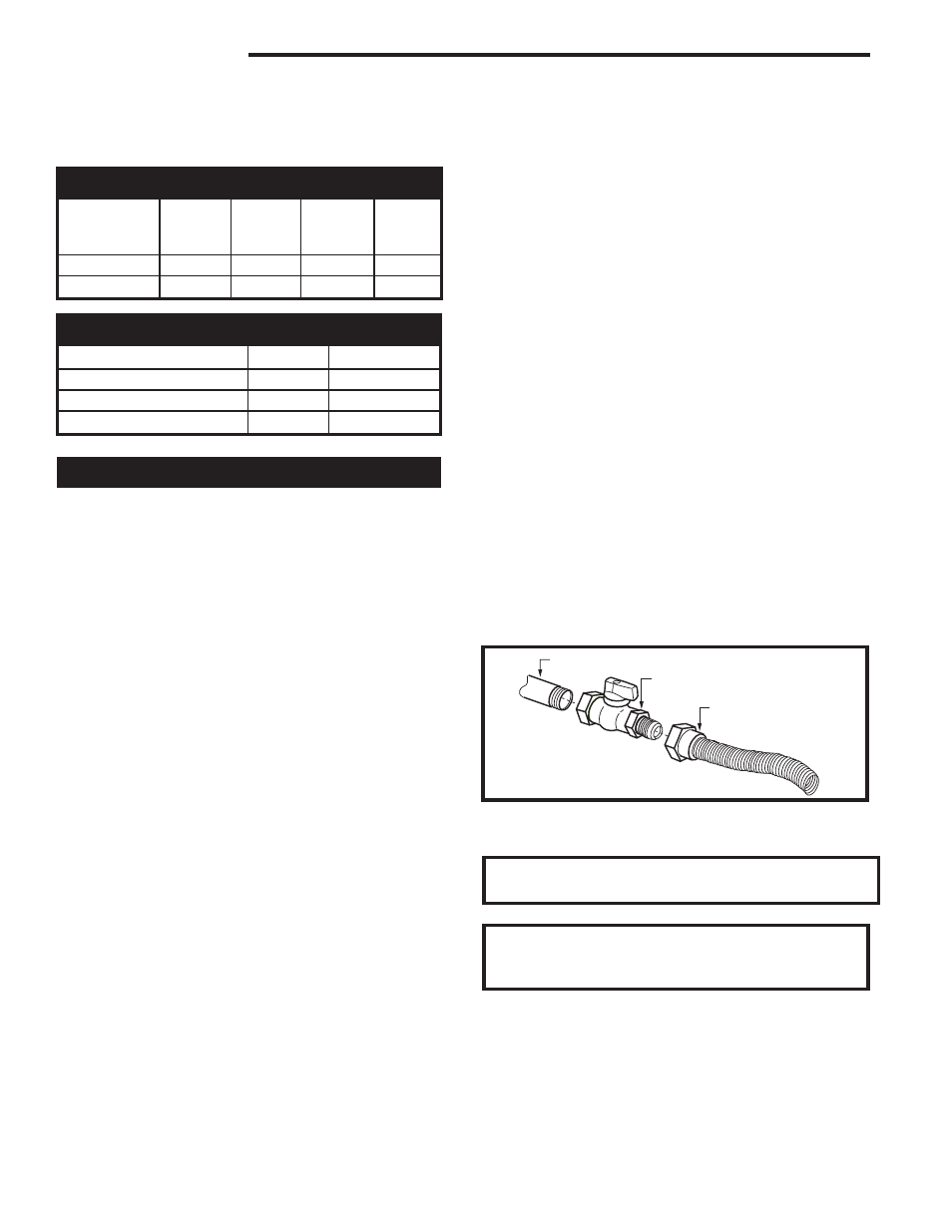
2. The gas control inlet is 3/8” NPT. Typical installation
layout for rigid pipe is shown on Page 8.
NOTE: All models are equipped with a flex tube
with a shut off valve having a 1/2” NPT inlet. The
flex line with shut off is shipped in the con-
trol valve compartment. Using two wrenches,
tighten the flexible tube at the shut off valve and
at the gas control.
3. When using a flex connector,* use only approved
fittings. When a union is installed, provide easy
access in it’s placement for servicing. Refer to gas
specification for pressure details and ratings.
4. When a vertical section of gas pipe is required for
the installation, a condensation trap is needed. In
Canada see CSA - B149.1 for code details. See the
National Fuel Gas Code ANSI Z223.1/NFPA 54 in
the USA.
5. For natural gas, a minimum of 3/8” iron pipe with
a gas supply pressure of 4.5” w.c. (from the gas
meter). Consult with local gas utility and ANSI223.1/
NFPA 54 if any questions arise concerning pipe
sizes.
6. Turn the gas supply to ‘ON’ and check for leaks. DO
NOT USE OPEN FLAME FOR THIS PURPOSE.
Use an approved leak testing solution.
7. The appliance and its appliance main gas valve
must be disconnected from the gas supply piping
system during any pressure testing of that system at
test pressures in excess of 1/2psig (3.5 KPa).
8. The appliance must be isolated from the gas sup-
ply piping system by closing its equipment shut off
valve during any pressure testing of the gas supply
piping system at test pressures equal to or less than
1/2psig (3.5KPa).
NOTE: The gas line connection may be made of 3/8”
minimum rigid pipe, 3/8” minimum copper pipe or an ap-
proved flex connector. Since some municipalities have
additional local codes, it is always best to consult your
local authorities and the current CSA-B149.1 installa-
tion code in Canada or National Fuel Gas Code ANSI
Z223.1/NFPA 54 in the U.S.A.
*Adhere to the following installation requirements in the State of Mas-
sachusetts:
• The installer must be a licensed plumber or gas fitter.
• Flex connectors must be Massachusetts approved, cannot
exceed 36” (914 mm) in length, must be a minimum 1/2” dia., and
may not penetrate a wall.
FP297A
INSTA VENT FREE
UVHB26 GAS SUPPLY
7/1/98
1/2” Gas Supply
1/2” NPT x 1/2” Flare Shut-off Valve
1/2” Flex Line
(from valve)
FP297a
Fig. 8 Typical gas supply installation.
IMPORTANT: Always check for gas leaks with a
soap and water solution. Do not use open flame
for leak testing.
Gas Inlet and Manifold Pressures
Natural
LP (Propane)
Minimum Inlet Pressure
4.5” w.c.
10.8” w.c.
Maximum Inlet Pressure 14.0” w.c.
14.0” w.c.
Manifold Pressure
3.5” w.c.
10.0” w.c.
WARNING: When purging the gas line, the glass
front must be removed.