Temco dv5200 series, Locating the fireplace, Framing and finishing – Temco Tool DV5200MB User Manual
Page 6
6
Temco DV5200 Series
78674
X
T175
rough opening
depth
vertical vent
12/3/03 djt
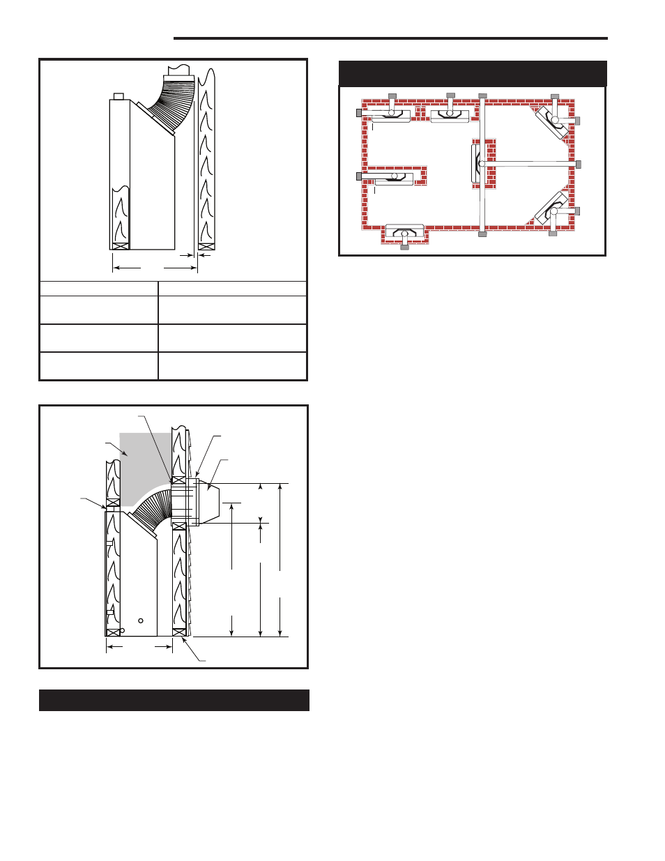
1” (25 mm)
Minimum Air Space
Clearance to Com-
bustible Materials
Vent System
“X”
TEMCO 4/7 Flex
23¹⁄₂”
(597 mm)
TEMCO 4/7 Rigid
24¹⁄₂”
(622 mm)
DuraVent 4/6-5/8 GS
23¹⁄₂”
(597 mm)
T175
Fig. 2 Minimum framing depths with vertical takeoff.
10���"
(273 mm)
Min.
T176
rough opening
depth horizontal
6/05 djt
35���”
(911 mm)
Ref. Flue
Outlet
�����
”
(781 mm)
41���”
(1054 mm)
21���”
(546 mm)
Firestop/Wall Sleeve
Combustible
Construction
Allowed
VEF (Vinyl Siding)
or BEF (Brick)
Extension flange
Vent Terminal
Standoff
T176
2 x 4 or 2 x 6 Framing
Fig. 3 Minimum framing dimensions with horizontal venting.
2. When the appliance is installed directly on carpeting,
tile or other combustible material other than wood
flooring, the appliance shall be installed on a metal
or wood platform.
3. Pull out the nail tabs which are located on each side
of the fireplace. Move the fireplace into position and
secure to the floor with screws or nails through the
holes provided in the bottom flanges of the side cas-
ing. After checking unit for squareness, secure top of
fireplace to the framing with screws or nails using the
nailing tabs provided.
4. Cold climate installation recommendation: when
installing this fireplace against a non-insulated exte-
rior wall or chase, it is recommended that the outer
walls be insulated to conform to applicable insulation
codes. Drywall should be installed around the unit to
prevent insulation from contacting the body.
Note: Never allow the vapor barrier to contact
the outer case of this fireplace or venting.
5. Drywall can be extended flush on the bottom, top
and to the outermost part of the sides of the fire-
place.
6. If you are installing the top vent unit with a 90° elbow
installed, the minimum clearance to combustibles
directly above the 90° elbow is 2” (51 mm).
7. Noncombustible materials such as brick and tile
can be extended across the face of the fireplace. If
brass trim kit is going to be installed, brick and tile
will have to be installed flush with the front of this ap-
pliance.
Locating the Fireplace
Y
E
A
B
C
D
F
Y
B
X
LU584-T
Locating unit
12/18/02 djt
X
Fig. 4 Locate gas fireplace.
A) Flat on wall
B) Cross Corner
C) As an Island
D) As a room divider E) Flat on wall corner F) Exterior wall
Island installation is possible as long as the horizontal portion of the
vent system does not exceed maximum recommended horizontal run
as outlined in the venting chart on Page 10. When you install your
fireplace as in position ‘B’, ‘D’ or ‘E’, (Fig. 1) a minimum of 1” (25mm)
clearance must be maintained from the perpendicular wall and the
front of the appliance.
Framing and Finishing
1. Choose a fireplace location and frame in accordance
with the fireplace dimensions specified on Page 4 of
this manual. When using a surround, the fireplace
must be flush to the wall. Also, allowances must
be made for drywall, tile or any other facing used
around the unit.