Temco dv5200 series – Temco Tool DV5200MB User Manual
Page 17
17
Temco DV5200 Series
78674
Do not locate vent terminal where excessive snow or
ice build up may occur. Be sure to check vent termina-
tion area after snow falls and clear to prevent accidental
blockage of venting system. When using snow blowers,
make sure snow is not directed towards vent termina-
tion area.
The TDV series is considered a “special vent system”.
Check with local codes or in the absence of same, with
CSA B149.1 installation codes regarding special vent
termination clearances.
NOTE: Flexible and rigid vent system components are
not interchangable unless otherwise specified in the
venting instructions.
NOTE: Additional venting information regarding clear-
ances, terminal locations, and safety information is
contained in the installation and operationg instructions
packaged with the appliance.
3³⁄₈" (86mm)
7⁷⁄₈"
(200mm)
8"
(203mm)
9¹⁄₈"
(232mm)
T193
offset and rise elbows
12/5/03 djt
TDV45S 45°
Elbow
90° Elbow
B
A
T194
vent offset
12/5/03 djt
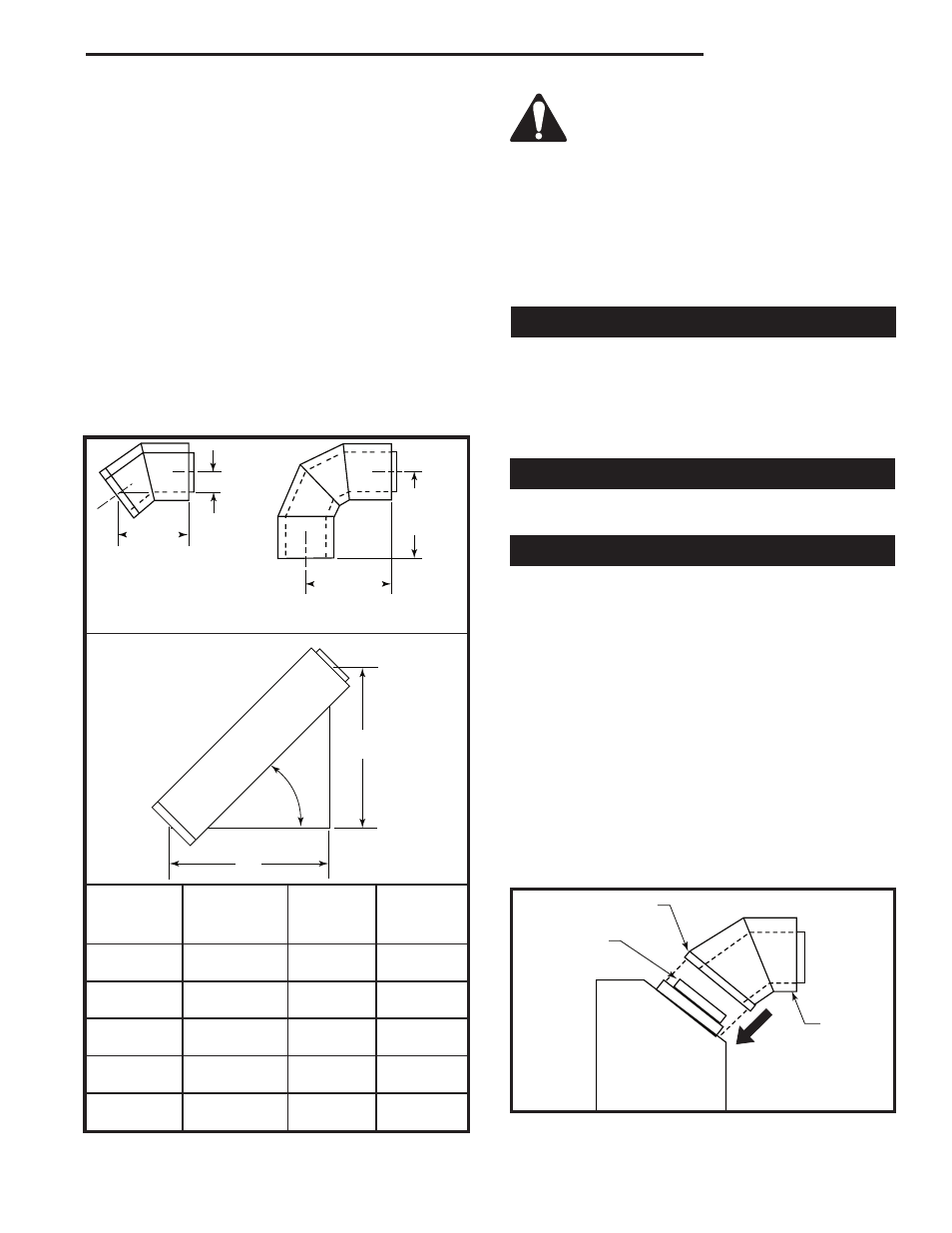
Vent Offset @ 45°
T193
45°
Installed
Vent Pipe
True Length
“A”
“B”
Component
Gain
Rise
Run
TDV6
4”
2¹¹⁄₁₆”
2¹¹⁄₁₆”
(102 mm)
(68 mm)
(68 mm)
TDV12
10”
7¹⁄₁₆”
7¹⁄₁₆”
(254 mm)
(179 mm)
(179 mm)
TDV18
16”
11⁵⁄₁₆”
11⁵⁄₁₆”
(406 mm)
(287 mm)
(287 mm)
TDV36
34”
24¹⁄₁₆”
24¹⁄₁₆”
(864 mm)
(611 mm)
(611 mm)
TDV48
46”
32¹⁄₂”
32¹⁄₂”
(1168 mm)
(826 mm)
(826 mm)
T194
IMPORTANT: Do not mix vent system compo-
nents with components for other vent systems.
NOTE: Use only venting systems and components
as certified with the appliance. Use of uncertified vent
systems or components will void the warranty and may
compromise the operation of the fireplace, its systems,
and components as certified with the appliance. Use
of uncertified vent systems or components will void the
warranty and may compromise the operation of the
fireplace.
Through the Roof (Vertical) Venting
When the venting penetrates a roof, the system must
be insalled in accordance with the current CSA B149.1
installation code (in Canada) or the current National
Fuel Gas Code, ANSI Z223.1/NFPA 54 (in U.S.A.).
SEE CHART FOR VERTICAL TERMINATION LOCA-
TION.
Elbows & Offsets - General
Each installation assures the use of one 45° elbow hori-
zontal or vertical (off top of unit).
Sidewall (Horizontal) Venting Information
1. Make sure fireplace location and termination location
are consistent with requirements for terminations
and vent runs.
2. Secure unit to the floor.
3. Locate vent opening in wall. Maintain 2” (51 mm)
clearance to top of vent from combustibles. Install
wall thimble per instructions supplied with Horizontal
Vent Kit. Refer to Pages 12 & 13, Figures 19 and 20
for wall thimble installation.
4. Attach vent components beginning with a TDV45S
elbow. Apply high temperature sealant to the out-
side leading edge of the fireplace flue pipe, then
install the TDV45S starter elbow and secure it to the
fireplace with the three (3) screws (provided) through
the outer pipe flange and into the fireplace 7” (178 mm)
dia. starter flange.
T196
Horizontal takeoff
12/5/03 djt
Screw Location
Apply Sealant
to Flue Pipe
Horizontal
Take Off
Illustrated
T196
Fig. 27 Apply high temperature sealant to outside of the flue
pipe.