Temco dv5200 series – Temco Tool DV5200MB User Manual
Page 23
23
Temco DV5200 Series
78674
Recommended Maximum Lead Length
(Double Wire)
When Using Wall Switch or Thermostat
Wire Size
Max. Length
14 ga.
50’ (15.2 m)
16 ga.
32’ (9.8 m)
18 ga.
20’ (6 m)
20 ga.
15’ (4.6 m)
22 ga.
10’ (3 m)
NOTE: Some Models are supplied with 15’ (4.6 m) of
double wire for use with a wall switch.
CAUTION: Do not wire 120V power to millivolt
switches or thermostats.
Managing Heat Output
The heat output from the appliance may be controlled
by adjusting the main gas valve. Reference lighting
instructions on Page 24 and chart on Page 33 showing
inputs at all the settings.
The main gas valve may be adjusted anywhere be-
tween high and low to give the desired combination of
flame aesthetics and heat output.
HI
LO
T155
PS24
hi/lo knob
11/10/03 djt
Turn knob clockwise
to increase flame
Turn knob
counterclockwise
to decrease flame
Fig. 37 Flame adjustment knob.
Fan Operation
The fan operates automatically - turn the knob on the
speed control to adjust to the desired speed. The fan
will turn on as the fireplace comes up to operating tem-
perature. After the unit has been turned off and the unit
cooled to below a useful heat output range the fan will
shut off automatically.
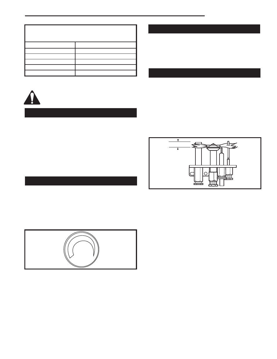
Flame Characteristics
It is important to periodically perform a visual check of
the pilot and burner flames. Compare them to Figure
38.
If the flame patterns appear abnormal, contact a quali-
fied service provider for service and adjustment.
Pilot Burner Adjustment
1. Adjust pilot screw to provide proper sized flame.
2. Leak test.
F584-703
Honeywell
& PSE
pilot flames
3/8” - 1/2”
(10 - 13 mm)
F584-703
Fig. 38 Correct flame appearance.
Burner On/Off Control
All models may be used with an optional wall switch
that turns the main burner on or off. Optional millivolt
thermostats (GFPMT) and remote control may be sub-
stituted for the wall switch (For installation of these op-
tions, detail instructions are provided with optional kits).
CAUTION: If the remote receiver is located in the gas
control area (under the firebox), clearance should be
below the firebox at least 2” (51 mm) to avoid high tem-
peratures (receiver should not be exposed to tempera-
tures exceeding 130°F).