Temco dv5200 series – Temco Tool DV5200MB User Manual
Page 27
27
Temco DV5200 Series
78674
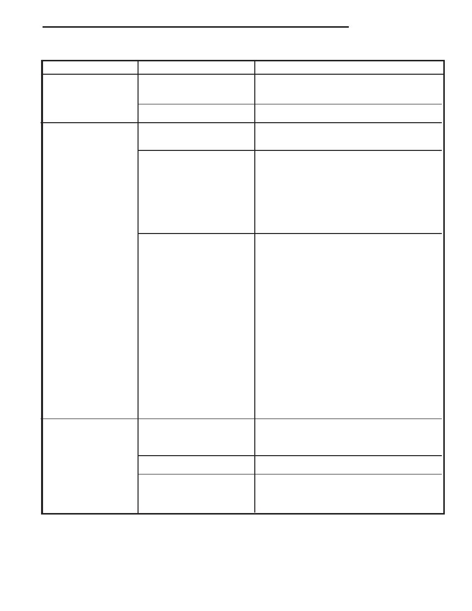
Problem
Possible Cause
Solution
System Checks
(continued)
Pilot not lit.
Light pilot and wait for thermo-generator to heat up
sufficiently to power the main operator. If pilot fails
to light, or hold, refer to above sections.
Control knob not in ON
Rotate OFF/PILOT/ON control knob to the ON posi-
position.
tion.
Thermostat/wall switch
Thermostat not in ON position.
Turn thermostat ON, and adjust temperature control
will not cycle main
to call for heat.
burner.
Thermo-generator output
After the pilot has been lit for approximately three
voltage not within design
minutes, and only the thermo-generator wire con-
parameters.
nected to the main operator head, measure the
voltage acrossTPTH and TP. This open circuit volt-
age should be between 500mv and 750mv. Tune the
pilot adjustment screw until the mv reding falls with-
in these parameters. (Counterclockwise increases
mv reading, clockwise decreases) If unable to meet
minimum requirements, repalce thermo-generator.
Defective thermostat or
(A) With the pilot adjusted properly, ( After the pilot
thermostat wiring
has been lit for approximately three minutes, and
only the thermo-generator wire connected to the
main operator head, measure the voltage across
TPTH and TP. This open circuit voltage should be
between 500mv and 750mv. Tune the pilot adjust-
ment screw until the mv reading falls within these
parameters. Counterclockwise increases mv read-
ing, clockwise decreases), place a jumper wire be-
tween TPTH and TH. Take a mv reading across the
TPTH and TP terminals on the valve. This closed
circuit voltage should not fall below 300mv. Record
reading.
(B) Remove jumper wire form the TPTH and TH
connections, and reconnect the thermostat wires to
the same terminals. Take the closed circuit voltage
as described in the previous step. If the mv reading
drops below 150mvm, excessive resistance exists
in the thermostat circuit, and must be isolated and
eliminated.
Thermostat/wall switch
Defective wall switch.
Repeat the above troubleshooting items covered
will not cycle mian
under “Defective thermostat or thermostat wiring”,
burner.
except substitute the words “wall switch” where the
word “thermostat” appears in the instructions.
Excessive wire resistance.
Make certain that all mv connections are made us-
ing wire of the proper size. (Reference Page 23).
Valve wired wrong.
Thermo-generator leads must be connected to the
TPTH and TP connections of the main operator.
Thermostat wires must be connected to the TPTH ,
and TH terminals of the valve.