Troubleshooting, Temco dv5200 series – Temco Tool DV5200MB User Manual
Page 25
25
Temco DV5200 Series
78674
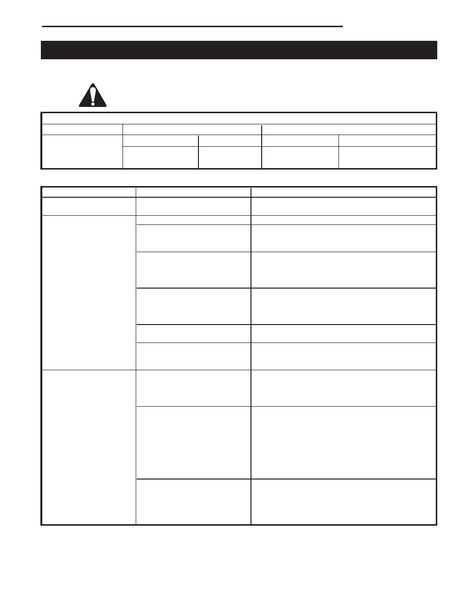
Troubleshooting
SIT Millivolt Valve
NOTE: Before troubleshooting the gas control system, be sure external shut off is in the “ON” position.
WARNING: Before doing any gas control service work, remove glass front!
Table 1
Valve Type
Main Operator
Safety Magnet
NOVA MV Plus
Minimum Voltage 145mV
Hold-in Current
Less than 285mA
Coil Resistance
2.25Ω ± 0.5Ω
Drop-out Current
Greater than 125mA
Coil Resistance
0.108Ω ± 0.003Ω
Problem
Possible Cause
Solution
Unit fails to operate
Batteries weak in remote unit
Replace batteries in both receiver and hand held
control
Pilot will not light.
Air in gas lines.
Bleed all air from gas lines.
Defective spill switch
Check for continuity across spill switch leads. Re-
place spill switch if excessive resistance is present,
or if circuit is electrically open.
Wrong inlet pressure.
With the main burner functioning, adjust the inlet
pressure regulator to supply gas to the appliance
within the design parameters of the appliance manu-
facturer. (Typically 7”NG, 11”LPG).
Defective spark electrode.
Replace piezo wire if insulation is cracked or the tip
is corroded.
Verify that the spark gap between the pilot and the
electrode is correct.
Defective piezo wire.
Replace piezo wire if insulation is damaged, or the
wire is broken or corroded.
Safety interlock function
Allow thermocouple to cool until the mv drops below
engaged.
the hold-in requirements of the safety magnet, (30
seconds or less). Re-light pilot.
Pilot will not hold.
Wrong inlet pressure.
With the main burner functioning, adjust the inlet
pressure regulator to supply gas to the appliance
within design parameters of the appliance manufac
turer. (Typically 7”NG, 11”LPG)
Pilot adjustment screw not
After the pilot has been lit for approximately three
properly adjusted.
minutes, and only the thermo-generator wire con-
nected to the main operator head, measure the volt-
age across TPTH and TP. This open circuit volt
age should be between 500mv and 750mv. Tune
the pilot adjustment screw until the mv reading
falls within these parameters. (Counter-clockwise
increases mv reading, clockwise decreases).
Thermocouple or
Make certain that the thermocouple and thermo-
thermo-generator not
generator are fully inserted and tightened into their
properly inserted into the pilot
receptacles in the pilot head. The thermocouple
housing
should be threaded into the valve hand-tight, plus
1/4 turn with wrench.
System Checks