Temco dv5200 series – Temco Tool DV5200MB User Manual
Page 26
26
Temco DV5200 Series
78674
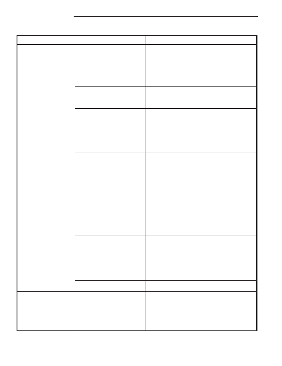
Pilot will not hold
Thermocouple or
With the thermocouple and thermo-generator tips
thermo-generator has film
cool, clean the upper 3/8” with a very fine emery
continued...
build-up on tip.
cloth.
Electrical resistance too high.
Using a very fine emery cloth, clean thermo-genera-
tor and thermocouple connections at valve. Tighten
thermocouple into valve hand-tight, plus 1/4 turn
with a wrench.
Defective thermocouple.
Verify that thermocouple is not kinked or damaged.
(mv Plus systems)
Check open circuit voltage of thermocouple. Voltage
should be between 18mv and 28mv. If voltage is
less than 14mv, replace thermocouple.
Defective thermo-generator.
After the pilot has been lit for approximately three
(Millivolt system)
minutes, and only the thermo-generator wire con-
nected to the main operator head, measure the volt-
age across TPTH and TP. This open circuit voltage
should be between 500mv and 750mv. Tune the
pilot adjustment screw until the mv reading falls
within these parameters. (Counter-clockwise
increases mv reading, clockwise decreases)
Defective safety magnet.
Verify operation of safety magnet in the following
(mv Plus systems)
manner.
(A) Depress and hold pilot button.
(B) Verify open-circuit thermocouple voltage as de-
scribed in previous step.
(C) Reconnect thermocouple to valve.
(D) Measure the Millivoltage between the solder
button on the base of the safety magnet, and the
valve body. If the mv reading is above 6mv for
vented appliances, or 8.5 mv for un-vented
appliances, and the safety magnet does not hold,
replace the valve.
(E) If closed circuit mv reading is the same as the
open circuit reading, the coil is electrically open.
Replace the valve.
Defective Safety Magnet
Verify operation of safety magnet in the following
(Millivolt system)
manner.
(A) Remove all wires from the terminals of the main
operator.
(B) Measure the electrical voltage between the term-
inals TPTH and TP. If the voltage is above 110mV
and the safety magnet does not hold, replace the
valve.
Pilot orifice blocked.
Replace orifice with a new orifice of the exact size
and type.
Pilot drops out.
Wrong pilot orifice.
Replace the orifice with a new orifice supplied
specifically for the appliance and gas type in
question.
No gas to main burner
Low gas pressure to appliance. With the main burner functioning, adjust the inlet
pressure regulator to supply gas to the appliance
within the design parameters of the appliance manu-
facturer. (Typically 7”NG, 11”LPG).
Problem
Possible Cause
Solution
System Checks
(continued)