Temco dv5200 series, Replace pilot orifice, Convert valve to lp – Temco Tool DV5200MB User Manual
Page 30
30
Temco DV5200 Series
78674
WARNING: Failure to position the parts in accor-
dance with these diagrams or failure to use only
parts specifically approved with this heater may
result in property damage or personal injury.
Replace Pilot Orifice
1. The pilot hood is held in place by spring pressure.
Remove the hood by pulling it directly up from the
pilot bracket. (Fig. 42)
2. Insert a 3/32” (4 mm) Allen wrench into the hexago-
nal keyway of the injector and rotate it counterclock-
wise until it is free of the injector journal. (Fig. 42)
T207
remove pilot hood
1/8/04 djt
Pilot Hood
Allen
Wrench
Conversion
Pilot
T207
Fig. 42 Remove pilot hood and orifice. Insert conversion
orifice.
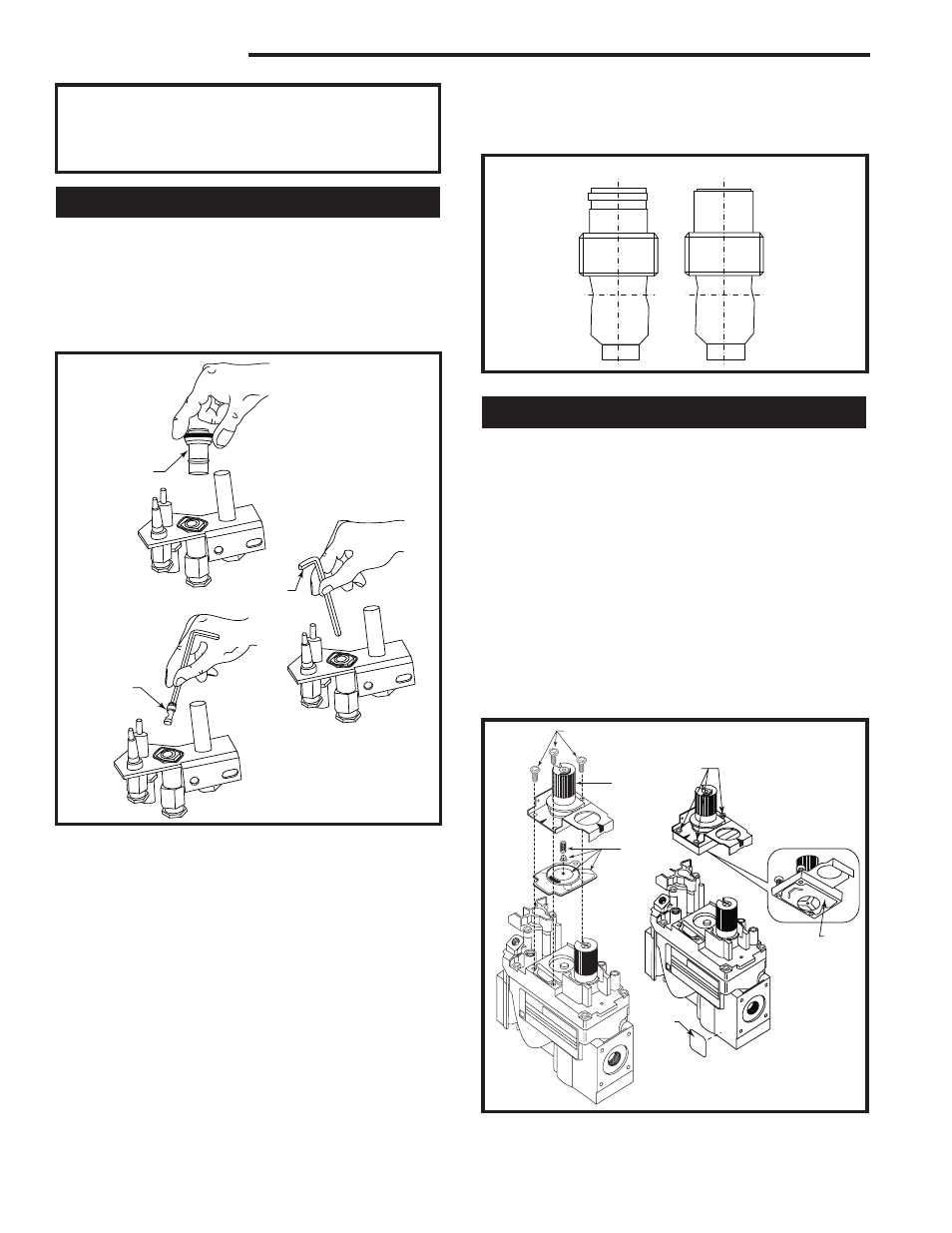
3. Verify the new injector is proper for the applica-
tion. The injector size is stamped on the side of the
injector near the top. LPG injectors have a groove
machined around their circumference near the top,
while the NG injectors do not have a groove. (Fig.
43) Install the conversion orifice furnished with unit
(Conversion Kit).
4. Insert the Allen wrench into the end of the injector.
Insert the injector into injector journal, and rotate
the injector clockwise until a torque of 9 in/lbs. Is
achieved. Replace the pilot hood by aligning the tab
n the base of the hood with the slot in the side of the
pilot journal. Push the hood down, directly onto the
pilot bracket. (Fig. 43) The hood must sit squarely on
the bracket for proper operation. Check to insure the
hood is properly seated onto the pilot bracket.
T208
conversion
injectors
1/8/04 djt
LPG
NG
T208
Fig. 43 Injectors.
Convert Valve to LP
1. Using a Torx T20 bit or slotted screwdriver, remove
and discard the three (3) pressure regulator mount-
ing screws (A), pressure regulator tower (B) and
diaphragm (C). (Fig. 44)
2. Insure the rubber gasket (D) is properly positioned
and install the new HI/LO pressure regulator assem-
bly to the valve using the new screws (E) supplied
with the kit. Tighten screws securely. (Fig. 44)
3. Install the enclosed installation label (F) to the valve
body where it can easily be seen.
4. Apply gas to system and relight appliance according
to manufacturer’s instructions.
5. With the main burner “ON”, test the new pressure
regulator assembly for leaks using a soap solution.
FC107
SIT820
valve conversion
10/03
A
B
C
OFF
PILO
T
ON
D
E
F
FC108
SIT
regulator
conversion
10/03
OFF
PILOT
ON
FC1007/108
Fig. 44 Remove mounting screws, pressure regulator tower
and diaphragm assebly, discard. Replace regulator.