Toro GREENKEEPER 212 User Manual
Page 29
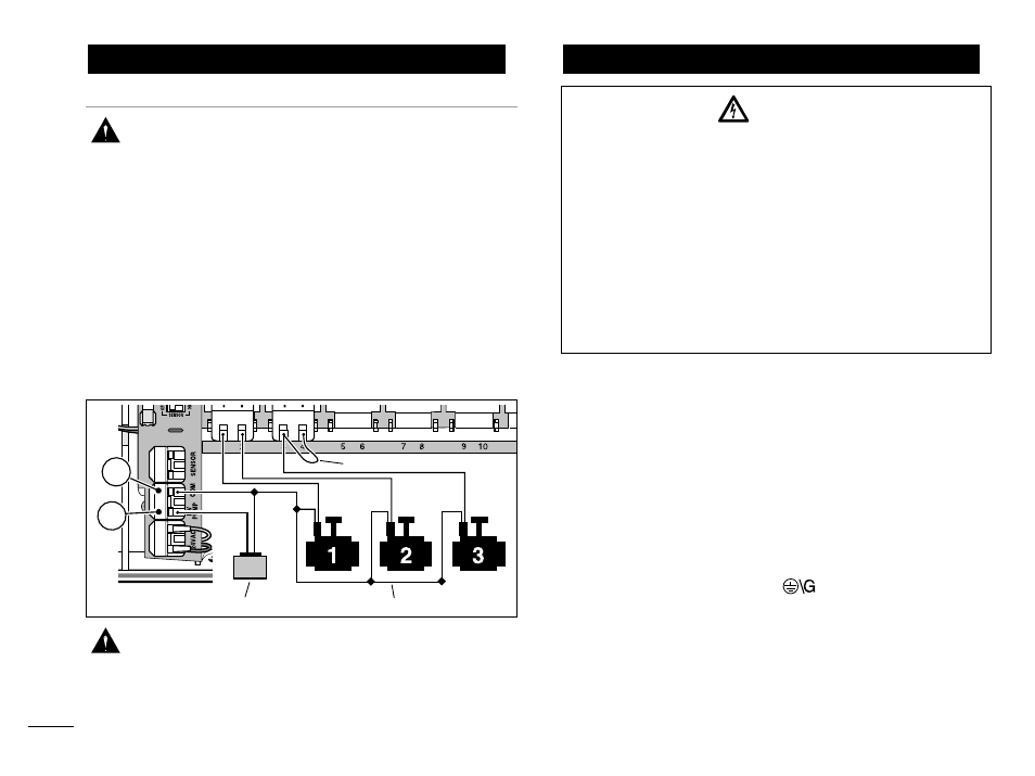
(Optional)
CAUTION: To prevent controller damage,
ensure the relay current draw does not exceed
0.30 Amps. Do not connect the controller
directly to the pump starter.
1. For pump relay wires, install a 1/2" (13mm) conduit
adapter and conduit.
2. Connect a wire pair to the pump relay terminals and
route the cable through the conduit and into the con-
troller housing.
3. Connect one wire to the terminal labeled COM (12).
Connect the remaining wire to the terminal labeled
PUMP/MV (13) as shown below.
CAUTION: To prevent pump damage due to
“dead-heading,” connect a jumper wire from any
unused station terminal to a station terminal with
a valve connected.
1. Route the power and equipment ground wires from the
power source, through the conduit and into the con-
troller transformer compartment.
Note: The controller terminal block accepts wire size
up to 12 AWG (4mm
2
).
2. Remove 3/8" (10mm) insulation from the wire ends.
3. Using a small flat blade screwdriver, secure the wires
as shown to the terminal block as follows:
Line or Line 1 (L1) to L, Neutral or Line 2 (L2) to N
and Equipment Ground to
.
4. Install and secure the transformer compartment
cover.
5. Apply power to the controller.
Connecting the Power Source
Connecting a Pump Start Relay
28
BATTERY
Pump Relay
Valve Common Wire
Jumper Wire
WARNING:
AC power wiring must be installed and connected
by qualified personnel only. All electrical compo-
nents and installation procedures must comply
with all applicable local and national electrical
codes. Some codes may require a means of discon-
nection from the AC power source installed in the
fixed wiring and having a contact separation of at
least 0.120" (3mm) in the line and neutral poles.
Make sure the power source is OFF prior to con-
necting the controller.
12
13