RuggedCom RX1512 User Manual
Page 30
Chapter 3
Installation
RUGGEDCOM RX1512
Installation Guide
24
SFP Optics – Installation, removal, and precautions
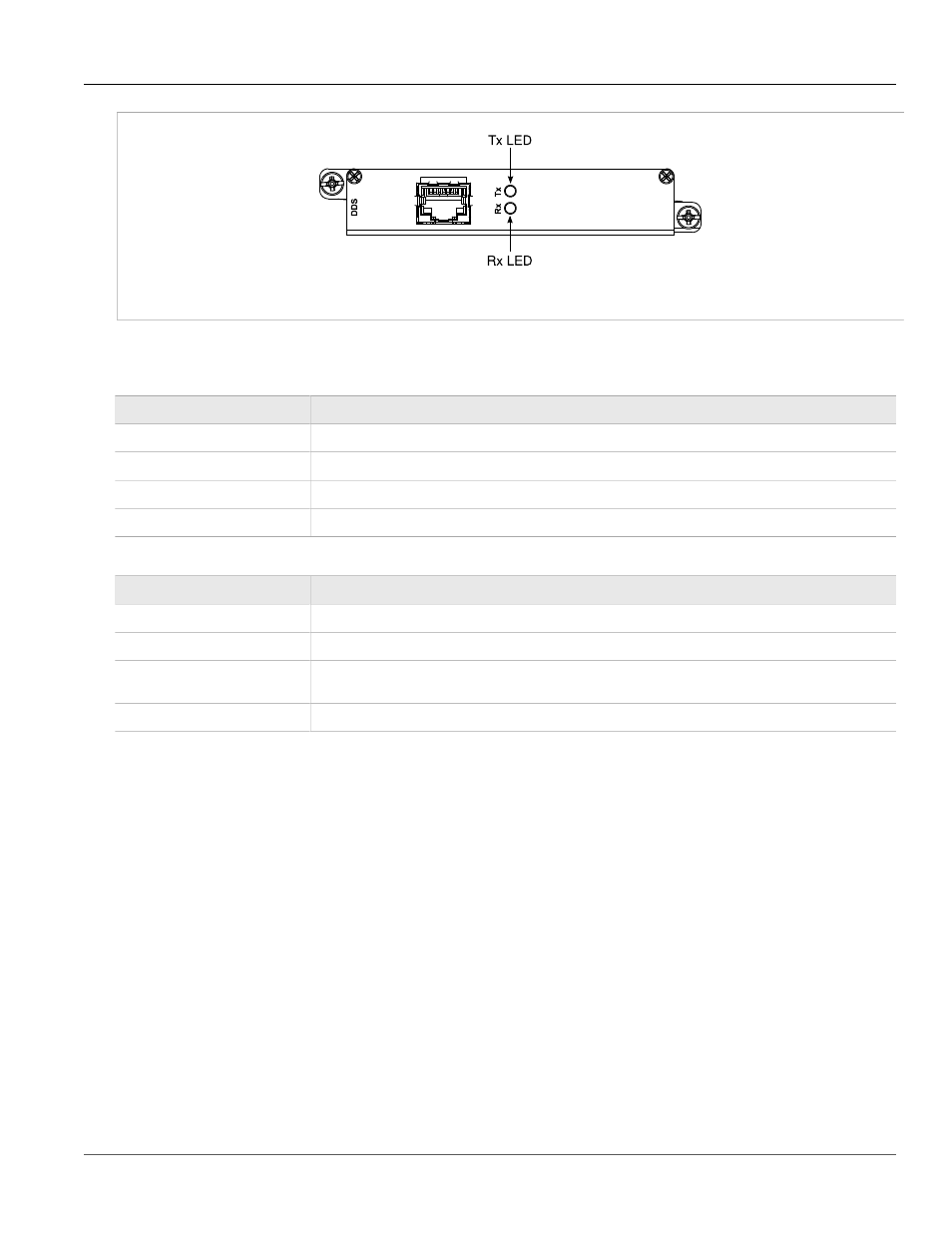
Figure 47: DDS Module Rx and Tx LED Indicators
The following tables describe the DDS module Rx and Tx LED status indications:
Table: DDS Rx LED Indications
Rx LED Color
Status
GREEN
Frame sync detected and signal OK.
YELLOW
Signal OK, but no frame sync.
RED
Loss of signal.
OFF
The interface is not enabled.
Table: DDS Tx LED Indications
Tx LED Color
Status
GREEN
The interface is enabled and remote device has no errors.
YELLOW
The interface is in loopback mode.
RED
Loss of signal or receiving any of OOS, UNM, or UMC codes: the remote device is out of service or has
problems with the signal.
OFF
The interface is not enabled.
Section 3.11
SFP Optics – Installation, removal, and
precautions
The RX1512 can be ordered with SFP (Small Form-factor Pluggable) pluggable optics modules. SFP modules
can be safely inserted and removed while the chassis is powered and operating. When inserting or removing
optics, observe the following precautions:
• Ensure that dust caps are mounted on SFP cages at all times, unless you are in the process of inserting or
removing an SFP module. The dust caps prevent the accumulation of residue or particles that might inhibit
proper operation.
• Ensure that you have properly discharged any possible electrostatic build-up to prevent electrostatic
discharges (ESD). This can be accomplished by proper grounding through an ESD wrist strap, or by touching
earth or chassis ground before installing or removing optical modules. ESD can damage or shorten the life of
optical modules when they are not plugged into a chassis.