Dc power supply wiring example, Critical alarm wiring, 3 dc power supply wiring example – RuggedCom RX1512 User Manual
Page 24: 3 critical alarm wiring, Critical alarm (failsafe) relay interface, Section 3.3, “critical alarm wiring, Section 3.2.3, “dc power supply wiring example
Chapter 3
Installation
RUGGEDCOM RX1512
Installation Guide
18
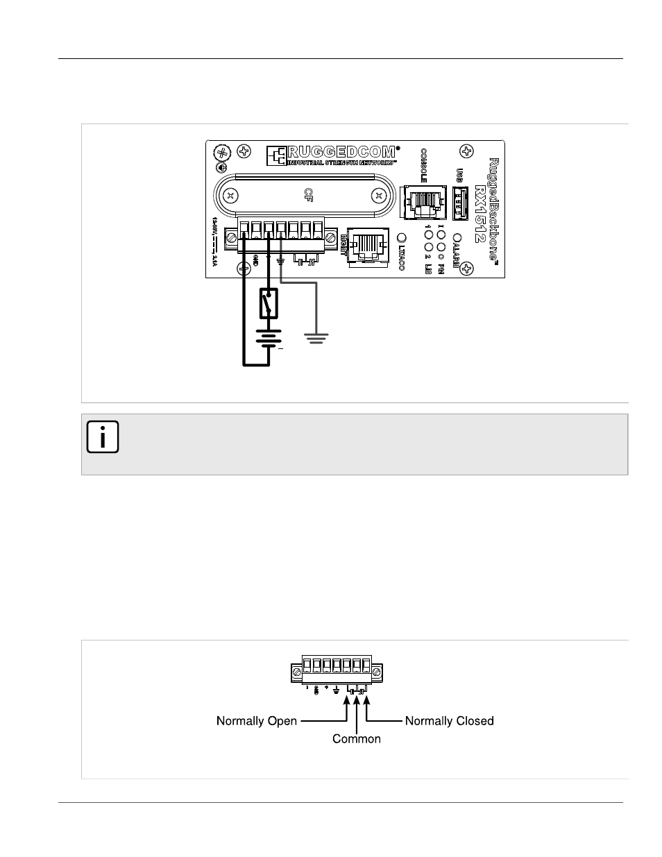
DC Power Supply Wiring Example
Section 3.2.3
DC Power Supply Wiring Example
+
Figure 37: Wiring for RX1512 DC Power Supply
NOTE
• It is recommended to provide a separate circuit breaker for the power supply.
• Equipment must be installed according to applicable local wiring codes.
Section 3.3
Critical Alarm Wiring
The Critical Alarm output relay signals critical error conditions that may occur on the RUGGEDCOM RX1512.
The contacts are energized upon power-up of the unit and remain energized unless a critical alarm condition is
detected. Relay connections are shown in the
Critical Alarm Relay Connector
diagram. You can configure control
of the relay output through the RX1512 user interface.
A common application for this output is to signal an alarm in case of a power failure.
Figure 38: Critical Alarm Relay Connector