Dds ports: rj45, Dds rx and tx led indications, 9 dds ports: rj45 – RuggedCom RX1512 User Manual
Page 29: 10 dds rx and tx led indications
RUGGEDCOM RX1512
Installation Guide
Chapter 3
Installation
DDS Ports: RJ45
23
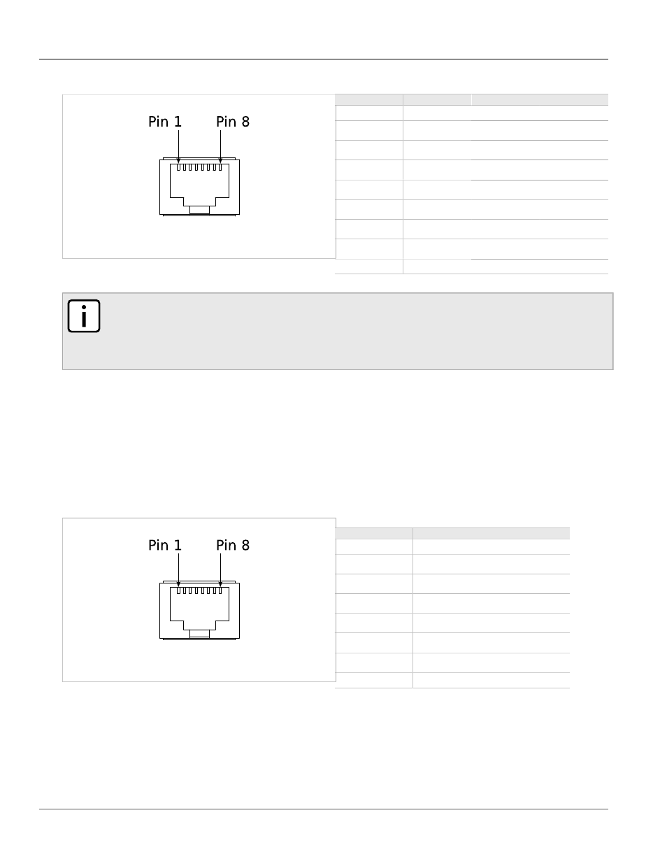
Figure 45: RJ45 Serial Pin Configuration
Table: RJ45 RS232/RS485/RS422 Serial Pin Assignment
Pin
RS232 Mode
RS485 Mode
RS422 Mode
1
—
—
RX-
2
Reserved
3
COM (Isolated GND)
4
COM (Isolated GND)
5
RX
—
RX+
6
TX
TX/RX +
TX +
7
CTS
—
—
8
RTS
TX/RX -
TX -
Shield
Chassis GND
NOTE
Pin 2 is reserved for future IRIG-B output. Do not connect Pin 2 at this time; doing so may cause
hardware damage. Pins 7 and 8 are connected internally. No internal termination is provided. In RS232
mode, these pins enter a high impedance state. A DTE that asserts RTS will see CTS asserted, but
hardware flow control is not performed on the port.
Section 3.9
DDS Ports: RJ45
The RX1512 supports DDS port line modules with RJ45 connections. The 56 kbps DDS port is compatible with
Bellcore standards. Each DDS module features a single 56/64 kbps DDS line interface with a standard RJ45
receptacle.
Figure 46: RJ45 DDS Pin Configuration
Table: RJ45 DDS Pin Assignment
RJ45 Pin
Description
1
R1: Transmit data to network (Ring 1)
2
T1: Transmit data to network (Tip 1)
3
NC
4
NC
5
NC
6
NC
7
T: Receive data from network (Tip)
8
R: Receive data from network (Ring)
Section 3.10
DDS Rx and Tx LED Indications
The DDS module features Rx and Tx LED indicators that display transmit and receive status.