6 extension connectors (j9-j13), Operational specifications – Renesas SH7149 User Manual
Page 38
Operational Specifications
3.1.6 Extension Connectors (J9-J13)
Rev.1.0 Dec 15, 2006
3-10
REJ10J0917-0100
3
3.1.6 Extension Connectors (J9-J13)
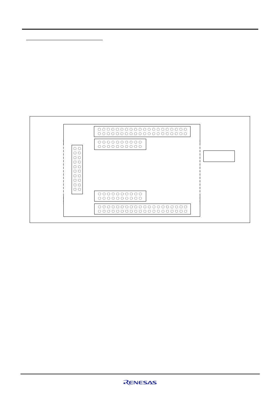
The M3A-HS49 includes extension connectors to which the I/O pins of the SH7149 are connected.
MIL Standard connectors can be connected to J9-J13, allowing the user to create extension board or monitor the
SH7149 bus signals.
The bus signals of SH7149 are connected to the terminal connector J10 (J13) through J9 (J12). There are J9 and
J12 for measuring the signals by measuring instrument. When an extension board is made, J10 and J13 of the
terminal connector are recommended to be used to prevent the waveform being distorted because of the reflection of
Figure3.1.8 shows a pin assignment of extension connector.
Board edge
19
20
1
2
J11
40
39
2
1
20
19
2
1
Top view of the
solder side
J13
J12
40
39
2
1
20
19
2
1
J10
J9
Board edge
Figure3.1.8 Pin Assignment of Extension Connectors (J9-J13)