Network Technologies USBV-x User Manual
Page 32
NTI UNIMUX SERIES USB KVM SWITCH
28
Note: To use this command protocol, the user is required to write a program that will send an entire command string all
at once, not character by character. Programs that send one character at a time (such as HyperTerminal) cannot be used
to control the UNIMUX. Alternatively, the user may use the NTI Switch Control Program or SerTest to control the
UNIMUX via RS232 (see page 27).
Legend
: (All numbers must be two digits)
SW
:
Switch (01-15) (Unit Address)
OP
:
Output (User) Port (01)
IP
:
Input (CPU) Port (01-MAXINPUTS)
:
Carriage Return (Hex 0xD)
Note: For units with one output (user) port, use 01 for the output selection.
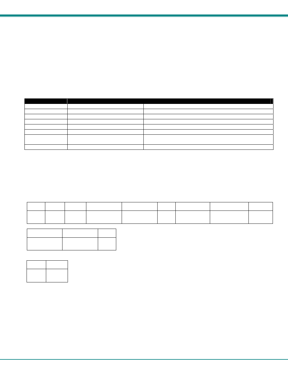
Command Definitions
Command String
Good Response
Description
CS SW,IP,OP
*
Connect Output (User) Port To specific Input (CPU) Port
RO SW,OP
*
Read Connection For Output (User) Port to Input (CPU) Port
RS SW
*
Internal Reset
RU SW
*
Read Unit Size
SS SW,00
*
Disable Autostatus feature (see below)
SS SW,01
*
Enable Autostatus feature (see below)
GO SW,OP
*
Read connection of an Output (User) Port to Input (CPU) Port
(different response format than RO command)
GM SW,00
*
Read connection matrix of all Output (User) ports
If the first field is not a known command (as listed above) or SW field is different from the unit address programmed at the DIP
switch (page 25), the command will be ignored. If the SW field corresponds to the unit address, but if the syntax is wrong after
this field, the switch will answer with a bad response ?
Syntax example:
CS 01,05,01
(insert the space and commas as shown)
which means “At the switch with unit address 01, connect CPU port 05 to user port 0
1
”
The switch will answer with:
∗
The HEX code representation of example above is:
Byte 1 Byte 2
Byte 3
Byte 4
Byte 5
Byte 6
Byte 7
Byte 8
Byte 9
‘C’
(0x43)
‘S’
(0x53)
Space
(0x20)
Switch
–
1st digit
(0x30)
Switch
–
2nd digit
(0x31)
‘,’
(0x2C)
Output
–
1st digit
(0x30)
Output
–
2nd digit
(0x35)
‘,’
(0x2C)
Byte 10
Byte 11
Byte 12
Input
–
1st digit
(0x30)
Input
–
2nd digit
(0x3
1
)
(0x0D)
Response:
Byte 1
Byte 2
‘
∗’
(0x2A)
(0x0D)
Autostatus
When Autostatus is enabled, any output (user) -to-input (CPU) connection change in the UNIMUX will cause an Autostatus
message to be sent via RS232 to the administrator. The format of the message would be "pc SW,OP:IP
Example of an Autostatus message:
pc 01,01:04
which means "At the switch with unit address 01, the output (User) (01) has changed connection to input (CPU) port 04."
Note: An Autostatus message to the administrator will be delayed by any RS232 traffic being received by the switch
from the administrator.
By default, Autostatus is disabled and must be manually enabled.