Option1 settings menu – NEC PX-42XM4A User Manual
Page 24
En-23
Option1 Settings Menu
Setting the on-screen menu
This sets the position of the menu, the display format
(horizontal or vertical) etc.
Example: Turning the DISPLAY OSM off
On “OPTION1” menu, select “OSM”, then press the MENU/
ENTER button.
The “OSM” menu appears.
On “DISPLAY OSM” of “OSM” menu, select “OFF”.
SEL.
ADJ.
RETURN
O S M
EXIT
D I S P L AY O S M
O S M A D J .
O S M A N G L E
O S M O R B I T E R
O S M C O N T R A S T
: O F F
: 1
: H
: O F F
: L O W
Information
Ⅵ
DISPLAY OSM settings
ON:
The informations on screen size, volume control,
etc. will be shown.
OFF:
The informations on screen size, volume control,
etc. will not be shown.
The DISPLAY button on the remote control will not
function either.
Ⅵ
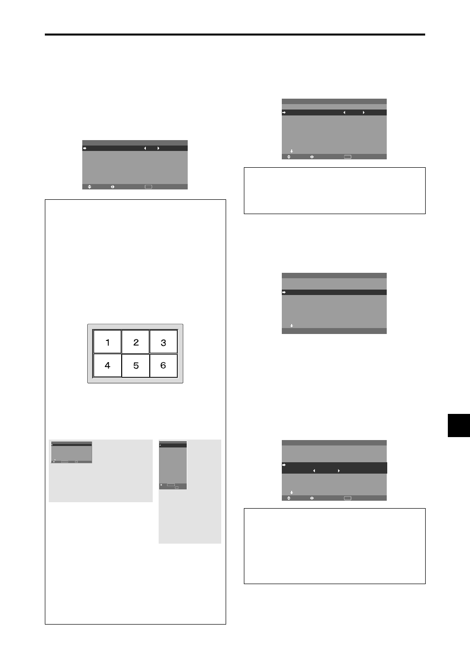
OSM ADJUST settings
Adjusts the position of the menu when it appears on
the screen.
The position can be set between 1 to 6.
Ⅵ
OSM ANGLE settings
Sets the display format (landscape “H” or portrait “V”).
When the unit is installed vertically set the OSM
ANGLE at “V”.
“H”
“V”
Ⅵ
OSM ORBITER settings
ON:
The position of the menu will be shifted by eight
dots each time OSM is displayed.
OFF:
OSM will be displayed at the same position.
Ⅵ
OSM CONTRAST settings
NORMAL:
OSM brightness is set to normal.
LOW:
OSM brightness is set to lower.
Setting the BNC input connector type
Select whether to set the input of the 5 BNC connectors to
RGB or Component.
Example: Set the BNC INPUT mode to “COMP.”
On “BNC INPUT” of “OPTION1” menu, select “COMP.”.
SEL.
ADJ.
RETURN
O P T I O N 1
1 / 4
O S M
B N C I N P U T
D - S U B I N P U T
R G B S E L E C T
: AU TO
H D S E L E C T
I N P U T S K I P
A L L R E S E T
N E X T PAG E
: C O M P.
: R G B
: 1 0 8 0 B
: O F F
: O F F
EXIT
Information
Ⅵ
BNC INPUT Settings
RGB:
Use the 5BNC terminals for RGB input.
COMP.:
Use the 3BNC terminals for component input.
SEL.
RETURN
O P T I O N 1
1 / 4
O S M
B N C I N P U T
D - S U B I N P U T
R G B S E L E C T
H D S E L E C T
I N P U T S K I P
A L L R E S E T
N E X T PA G E
: R G B
: R G B
: A U TO
: 1 0 8 0 B
: O F F
: O F F
EXIT
MENU/ENTER
OK
: R G B
: R G B
: AU TO
: 1 0 8 0 B
: O F F
: O F F
1024
768
EXIT
SEL.
RETURN
MENU/ENTER
OK
O P T I O N 1
O S M
B N C I N P U T
D - S U B I N P U T
R G B S E L E C T
H D S E L E C T
I N P U T S K I P
A L L R E S E T
Checking the signal being transmitted to
RGB1 terminal
Use this to confirm the signal being transmitted to the
RGB1 terminal.
It is set to RGB and can not be adjusted.
C A N N OT A D J U S T
O P T I O N 1
1 / 4
O S M
B N C I N P U T
D - S U B I N P U T
R G B S E L E C T
: AU TO
H D S E L E C T
I N P U T S K I P
A L L R E S E T
N E X T PAG E
: R G B
: R G B
: 1 0 8 0 B
: O F F
: O F F
Setting a computer image to the correct RGB
select screen
With the computer image, select the RGB Select mode
for a moving image such as (video) mode, wide mode or
digital broadcast.
Example: Setting the “RGB SELECT” mode to
“852
ן
480 ”
On “RGB SELECT” of “OPTION1” menu, select
“852
ן480”.
SEL.
ADJ.
RETURN
O P T I O N 1
1 / 4
O S M
B N C I N P U T
D - S U B I N P U T
R G B S E L E C T
: 8 5 2
ן
4 8 0
H D S E L E C T
I N P U T S K I P
A L L R E S E T
N E X T PAG E
: R G B
: R G B
: 1 0 8 0 B
: O F F
: O F F
EXIT
Information
Ⅵ
RGB SELECT modes
AUTO:
Select the suitable mode for the specifications
of input signals as listed in the table “Computer input
signals supported by this system” on page En-40.
The others:
The available resolutions are shown.
See page En-40 for the details of the above settings.