Nuvo Stereo System User Manual
Page 28
20
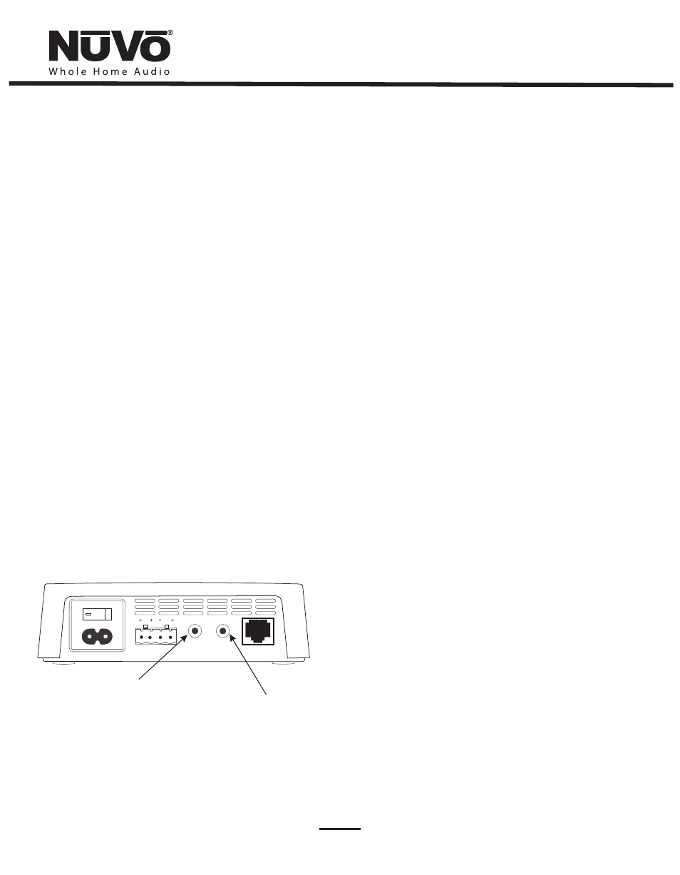
Line Input
The NV-RVFZA50S has a built-in “Line Input” on the back panel. This
is a very useful feature for allowing the internal 50W zone amplifier
to amplify any local source to the attached zone speakers, as shown
in fig. 20. This is a “smart” input and will recognize a 3.5mm mini
stereo input plug and automatically display a “Local Source”
selection on the zone controller. This enables the local source to be
selected and volume controlled from the NuVo Control Pad. The local
audio input can be set at variable as an either variable iPod, Mp3,
computer or other devices with headphone outputs. It can also be
fixed for many TV lineouts. Individual audio selections for the local
source must be made at the source. Those will not be available
through NuVoNet.
100-240V~50-60Hz 50W
SPEAKER OUTPUT
NuVoNet
LINE
INTPUT
LINE/HP
OUTPUT
Line/HP Output
A second 3.5mm mini stereo output is also available. This is useful as
a headphone jack particularity with tabletop or desktop
installations, as shown in fig. 21. By default, this is a variable output
for most headphone applications, or it can be switched to a fixed a
fixed output in the “Advanced Zone Settings” menu or in the “Zones”
tab of the Configurator software. The most common use for this
connection is as a lineout to an additional amplifier or receiver that
has its own volume control.
Warning: Excessive volume through a headphone device can
cause permanent damage or loss of hearing.
The Line input requires
a stereo mini connection
from the local source output
The Line/HP Output requires
a stereo mini connection for
headphones or additional
amplification.
5.0 Setting the Zone HomePlug Channel
If the HomePlug Channel on the Main Source Hub has been changed
to one other than A, see
section 6.6. Using the Configurator
Software, System Settings,
then you must make sure that each
Zone Amplifier is set to match.
Before setting the HomePlug Channel, the desired Zone Number
must be set, (see Section
3.2 Properly installing the Renovia Zone
Amplifier or 4.1 Properly Installing the Freestanding Renovia
Zone Amplifier
).
To set the HomePlug Channel, use a small screwdriver to turn the
zone address rotary switch, either clockwise or counterclockwise, to
the appropriate channel letter,
A, B, C,
or
D
as shown in Fig. 21,
showing the zone set on HomePlug channel B
.
Wait for the green
“Control” LED to light; then within three seconds of the green LED
turning on, turn the switch back to the desired zone number
previously set, as shown in Fig 22, showing the zone set on number
6. The Zone Amplifier will reboot. You will see the green
Control
LED
flash once for channel A, twice for channel B, three times for channel
C and four times for channel D. The Zone Amplifier should then
connect with the Main Source Hub and the attached Control Pad will
reinitialize.
Note the process is the same for the NV-RVZAF50S Freestanding
Zone Amplifier using the rotary switch located on the bottom of the
amplifier. The easiest way to see the response of the Control LED is to
turn it upside-down and view it through the adjacent ventilation
holes.
You can always verify the set HomePlug Channel by using a small
screwdriver or paper clip to press the
RST,
Reset button located on
the NV-RVZA50 or by turning the “Power” button off and back on, on
the NV-RVZAF50S. The
Control
LED will flash indicating the current
channel setting, as shown in Fig. 23.
Fig. 20