Installing the nv-rvzaf50s zone amplifier – Nuvo Stereo System User Manual
Page 27
An inset plug on the Power Supply will mate with a plug on the Zone
Amplifier. Once in place, secure the Zone Amplifier to the Power
Supply with four screws and install the finished cover plate. This is
held in place with four magnets and a single set screw on the
bottom. It can also be painted to match the wall color. When the
Zone amplifier has been addressed and installed, the zone is now
active as part of the system.
When power is restored to the associated outlet, you will see an
amber power LED. The green “Control” LED will flash when control
messages are sent to or received from the Main Source Hub, and the
blue “Audio Stream” LED will light when an audio signal is received
from the Main Source Hub.
4.0. Installing the NV-RVZAF50S Zone Amplifier
An easy to install solution for zone amplification is the NV-RVZAF50S
Freestanding Renovia Zone Amplifier. This is an external component
with a built-in power supply and detachable AC electrical cord.
When installed, the Freestanding version of the Zone Amplifier is
identical in operation to the In-wall version. The obvious application
is for any zone where it is not practical to install in a wall.
Choosing the Best Location for the NV-RVZAF50S
Like the in-wall Zone Amplifier, any outlet that has tested as Good or
Marginal with the SAT Tool will suffice as a zone location. Consider
outlets that are easily accessible if you are intending to use In-wall or
in-ceiling speakers or if you are installing one of the in-wall Control
Pad options for the zone.
4.1 Properly Installing the Freestanding Renovia Zone
Amplifier
The installation of the Freestanding Zone Amplifier is a relatively
simple operation. Plug it into the desired outlet. You will see the
“Power” LED on the leading edge of the amplifier component light.
You will also see the “Control” LED begin to flash as it communicates
with the installed Source Hub.
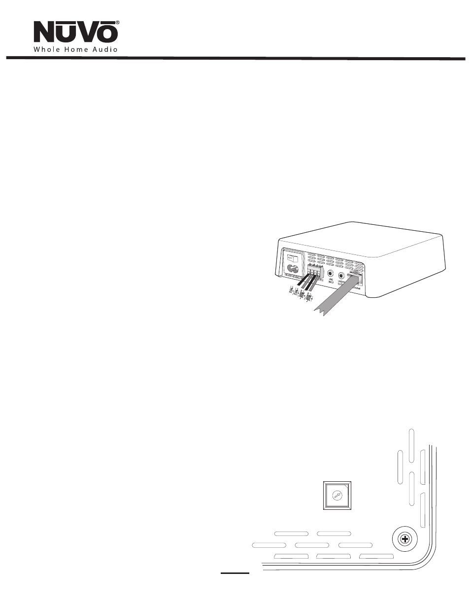
You are now ready to make the speaker and optional Control Pad
connections. The speaker connection is made through the included
modular phoenix connector. The termination is from left to right,
left – , left +, right –, right + . Plug the terminated connector into
the speaker input on the back of the NV-RVZAF50S, as shown in fig.
18.
If one of NuVo’s in-wall Control Pad options is going to be included in
the installation, then a CAT5 connection must be made at the RJ-45
connection labeled “NuVoNet”, also shown in fig. 18.
The next step in the installation is to set the zone address. This is
done using the multi-position rotary switch on the bottom of the
NV-RVZAF50S
. This switch setting, 1 - 8 should
correspond with the number assigned for that zone in the
Configurator software, see section 6.5 Zones. Any Control Pad
attached to that Zone Amplifier will assume that zone’s address. This
procedure can be done with the NV-RVZAF50S unplugged from the
AC as well.
, as shown in fig. 19
ZONE
1 2
D
3
4
C
5
B
6
A
7
8
Fig. 18
Fig. 19
19