Wire configuration, Wire configuration -3 – National Instruments Module SCXI-1503 User Manual
Page 16
Chapter 2
Connecting Signals
© National Instruments Corporation
2-3
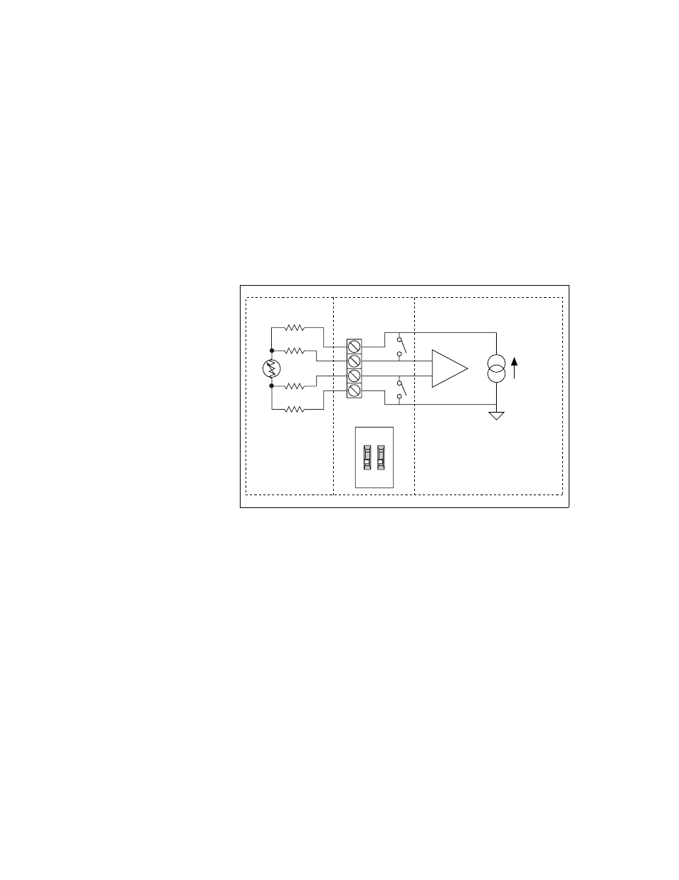
4-Wire Configuration
The 4-wire configuration, also referred to as a Kelvin connection, is shown
in Figure 2-1. The 4-wire configuration uses one pair of wires to deliver the
excitation current to the resistive sensor and uses a separate pair of wires to
sense the voltage across the resistive sensor. Because of the high input
impedance of the differential amplifier, negligible current flows through
the sense wires. This results in a very small lead-resistance voltage drop
error. The main disadvantage of the 4-wire connection is the greater
number of field wires required.
Figure 2-1. 4-Wire Resistive Sensor Connected in a 4-Wire Configuration
External Sensor
SCXI-1306
+
–
SCXI-1503
Channel X
IEX+
AI+
AI–
IEX–
I = 100 µA
ON
CH X
R
L3
R
L2
R
L1
R
L4
R
T
- Instrument Driver NI-DMM (12 pages)
- 24-Bit Half/Full-Bridge Analog Input Module NI 9237 (36 pages)
- NI PXIe-8105 (76 pages)
- PXI NI 5401 (60 pages)
- Fieldpoint CFP-2210 (38 pages)
- NI 781xR (48 pages)
- NI 6233 (180 pages)
- 6508 PCI-DIO-96 (93 pages)
- PXI/CompactPCI Embedded Computer NI PXI-8108 (83 pages)
- NI 9233 (34 pages)
- NI USB-9219 (25 pages)
- GPIB-PC (262 pages)
- cFP-RTD-122 (15 pages)
- USB device 625x (23 pages)
- Isolated Analog Input Modules SCC-AI01 (18 pages)
- NI PCI-6111 (118 pages)
- NI USB-6008 (32 pages)
- PC-DIO-24 (75 pages)
- NI 9474 (31 pages)
- NI 6013 (109 pages)
- PXI-1428 (46 pages)
- NI PCI-5911 (51 pages)
- 2 SD Card Memory Module NI 9802 (16 pages)
- cFP-20xx (24 pages)
- NI USB-9234 (23 pages)
- NI 9871 (24 pages)
- Interface Device NI PCI-1426 (35 pages)
- AT E Series (184 pages)
- 9211A (19 pages)
- Module NI PXI-8250 (39 pages)
- 8330 Series (30 pages)
- NI PXIe-8360 (40 pages)
- Deterministic Ethernet Expansion Chassis NI 9144 (65 pages)
- NI 6509 (23 pages)
- NI MATRIXx Xmath (127 pages)
- NI 9481 (23 pages)
- Monochrome Image Acquisition Device NI 1410 (34 pages)
- VXI-1394 (74 pages)
- NI PXI-8104 (69 pages)
- NI 9235 (38 pages)
- 370620B-01 (17 pages)
- FP-RTD-124 (15 pages)
- VXI-USB (61 pages)
- NI PCI-8254R (45 pages)
- Interface Device NI PCI-8254R (16 pages)