Powerware 9395 UPS and Plus 1 UPS 650825 kVA User Manual
Page 97
INSTALLING OPTIONS AND ACCESSORIES
EATON Powerware
®
9395 UPS (650–825 kVA) Installation and Operation Manual
S 164201725 Rev 2 www.powerware.com
5−5
UPS 1
UPS 2
UPS 3
UPS 4
CAN
(If Installed)
(If Installed)
Pull Chain
NOTE This drawing is for distributed bypass wiring purposes and is not a floor layout plan. UPSs can be placed in any physical order.
Figure 5-3. Distributed Bypass System Can and Pull−Chain Simplified Interface Wiring
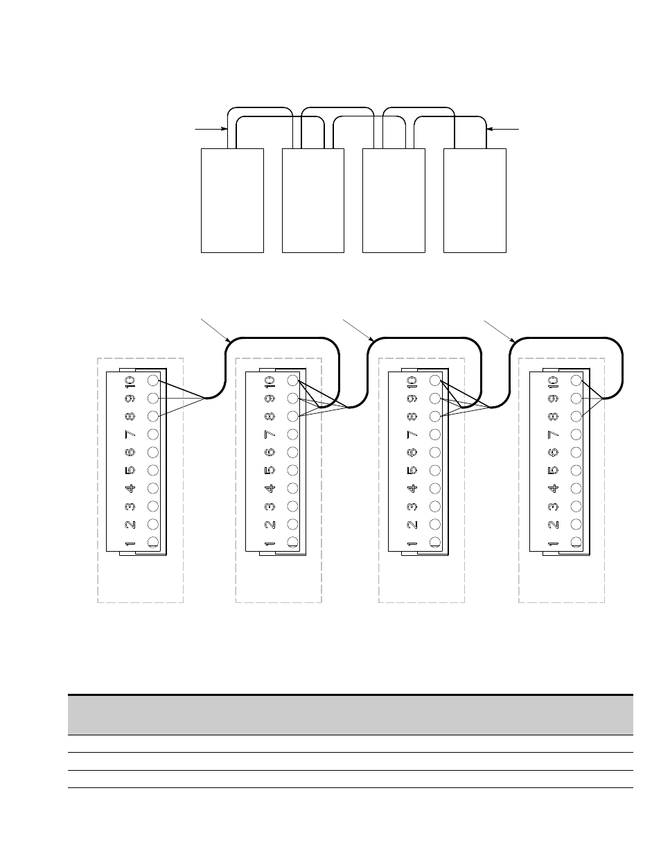
Shielded Twisted Pair
Shielded Twisted Pair
Shielded Twisted Pair
UPS 1
CAN Bridge Card J3
UPS 2
CAN Bridge Card J3
UPS 3
CAN Bridge Card J3
(If Installed)
UPS 4
CAN Bridge Card J3
(If Installed)
NOTE External CAN connections between UPSs require shielded twisted pair wire.
Figure 5-4. Distributed Bypass System UPS CAN Wiring without MOBs
Table 5-2. CAN Bridge Card Wiring Terminations
From
UPS 1 CAN Bridge Card
To
UPS 2 CAN Bridge Card
To
UPS 3 CAN Bridge Card
(If Installed)
To
UPS 4 CAN Bridge Card
(If Installed)
J3–8 (L)
J3–8 (L)
J3–8 (L)
J3–8 (L)
J3–9 (H)
J3–9 (H)
J3–9 (H)
J3–9 (H)
J3–10 (Shield)
J3–10 (Shield)
J3–10 (Shield)
J3–10 (Shield)