Through figure 4-32 – Powerware 9395 UPS and Plus 1 UPS 650825 kVA User Manual
Page 83
UPS SYSTEM INSTALLATION
EATON Powerware
®
9395 UPS (650–825 kVA) Installation and Operation Manual
S 164201725 Rev 2 www.powerware.com
4−37
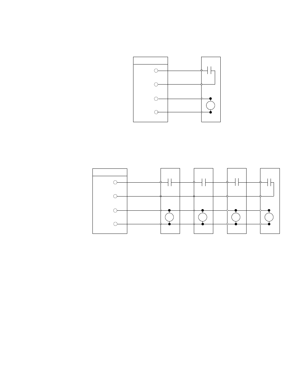
Battery
Disconnect
TB1
Battery Aux
Battery Aux Common
48 Vdc Battery Shunt Trip +
48 Vdc Battery Shunt Trip –
UPS
ST
5
6
7
8
NOTE Battery aux and DC shunt trip wiring should be a minimum of 18 AWG.
48 Vdc
Figure 4-31. Typical Battery Interface Connection – Common Battery System
UPM 1
Battery
Disconnect
TB1
UPS
ST
UPM 2
Battery
Disconnect
ST
UPM 4
Battery
Disconnect
ST
UPM 3
Battery
Disconnect
ST
48 Vdc
Battery Aux
Battery Aux Return
48 Vdc Battery Shunt Trip
+
48 Vdc Battery Shunt Trip
−
5
6
7
8
NOTE Battery aux and DC shunt trip wiring should be a minimum of 18 AWG.
Figure 4-32. Typical Battery Interface Connection – Separate Battery System