Powerware 9395 UPS and Plus 1 UPS 650825 kVA User Manual
Page 106
INSTALLING OPTIONS AND ACCESSORIES
EATON Powerware
®
9395 UPS (650–825 kVA) Installation and Operation Manual
S 164201725 Rev 2 www.powerware.com
5−14
NOTE Setup of the Powerware Hot Sync CAN Bridge Card must be performed by an authorized Eaton
Customer Service Engineer. Contact an Eaton service representative to schedule a date.
9.
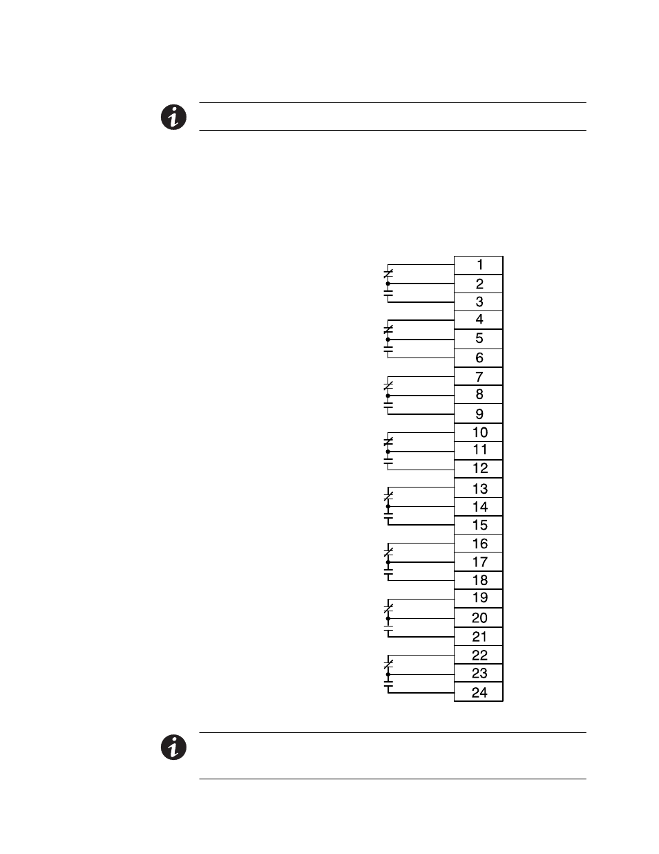
Install wiring between the SCM II terminal block TB2 and the monitoring
equipment. See Figure 5-10 for terminal block location and Figure 5-11 for
terminal assignments.
10. Close the front door and secure the latch.
11. Restart the UPS. See Chapter 7, UPS Operating Instructions," for startup
instructions.
System Normal
No Redundancy
On Generator
Bypass Not Available
On Battery
UPS Alarm
On Bypass
Shutdown Imminent
Figure 5-11. Supervisory Contact Module II TB2
NOTE Supervisory contacts are rated at 2.0A at 28 Vdc or 120 Vac and 0.15A at 115 Vdc.
NOTE Supervisory contacts require an external power supply. Internal 24 Vdc is not capable of supplying
contact current.