Operating modes – Powerware 9150 User Manual
Page 45
Operation
41
Powerware
®
9150 User’s Guide
:
www.powerware.com
Description
Status
LED
OVERTEMP
On or
Blinking
One of the main UPS components is too hot or the fan has
failed.
SERVICE
Blinking
Battery failure, fan failure, or configuration error exists.
Contact your service representative. See “Service and Support”
on page 57.
ALARM
Blinking
There is a UPS alarm condition. See Chapter 6,
“Troubleshooting” on page 55 for additional information.
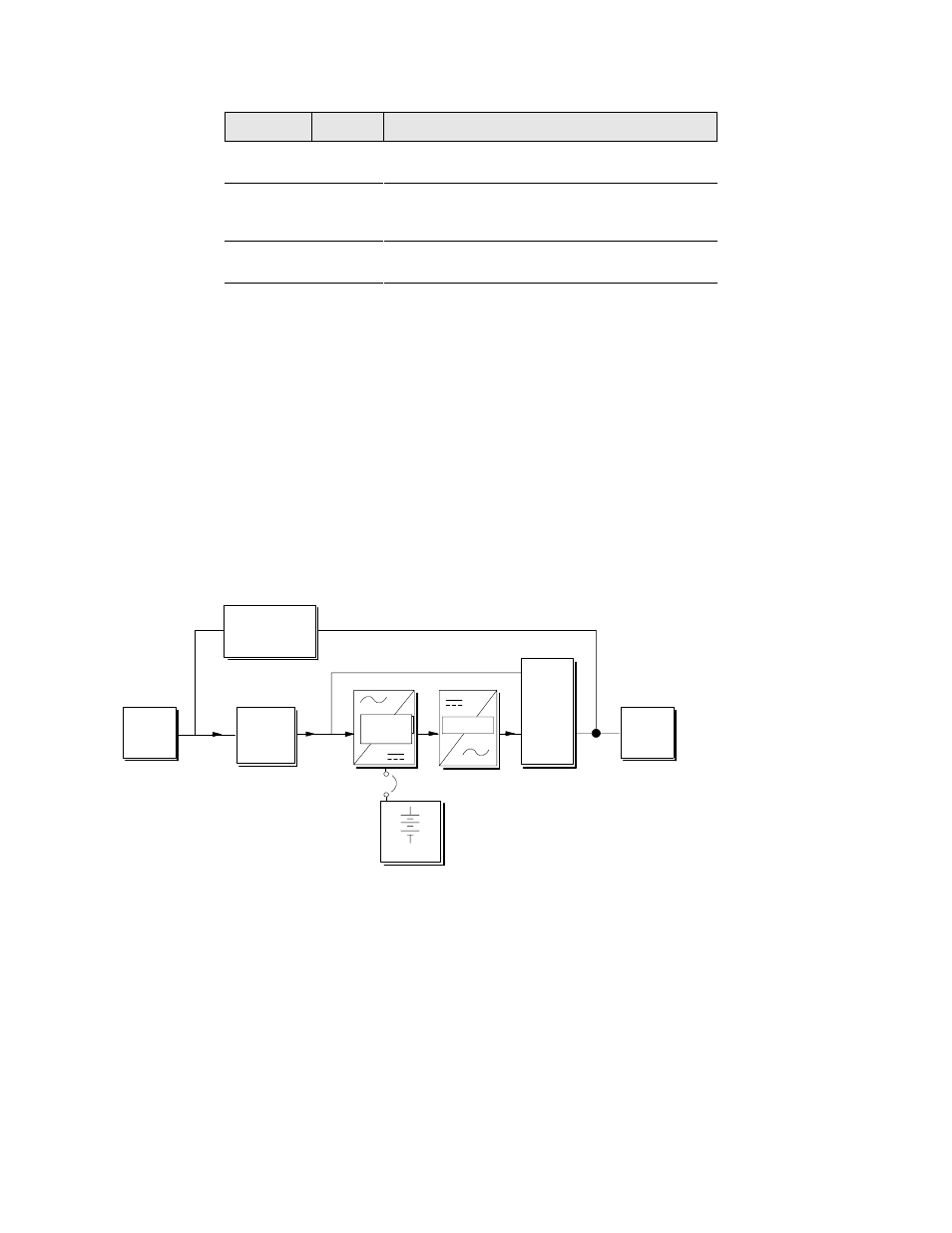
Operating Modes
The Powerware 9150 block diagram, shown in Figure 16, consists of
several modules, each having its own functions:
: The rectifier/charger converts AC-power to DC-power and keeps the
battery bank fully charged.
: The inverter converts DC-power back to AC-power, which is
delivered to the load.
: The Static Bypass switch transfers the load to bypass when the
inverter is overloaded or cannot power the load.
: The filter protects the load from disturbances in the utility when
power is supplied through the Static Bypass switch.
: The Maintenance Bypass switch is used to bypass the UPS to utility
power during maintenance, service, or startup.
Rectifier/
Charger
Filter
Battery
Inverter
Output
Maintenance
Bypass Switch
Utility
Power
Static
Bypass
Switch
Figure 16. Block Diagram of the Powerware 9150