Powerware 9150 User Manual
Page 27
Installation
23
Powerware
®
9150 User’s Guide
:
www.powerware.com
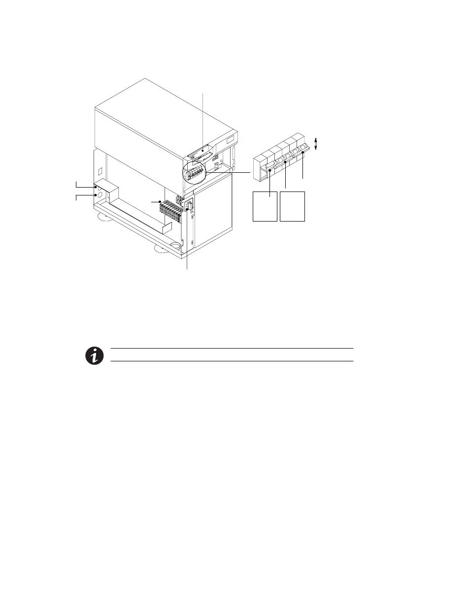
6. Verify that the UPS battery breaker CB1 and optional CB2 are in
the OFF position (see Figure 6).
Terminal
Block
Output
Conduit
Access
Maintenance
Bypass Switch
Input
Conduit
Access
UPS ON/OFF Switch
and Indicators
ON
OFF
F1
Battery
Neutral
Fuse
CB1
Internal
Battery
Breaker
CB2
(Optional)
External
Battery
Breaker
Figure 6. UPS Front and Side View
7. Hardwire the input (TB1-1 through TB1-4) and output (TB1-6
through TB1-9) terminations for the UPS. See the following
hardwired terminations table for specifications. See Figure 7 for
a detailed view of the terminal blocks.
NOTE The input neutral must be wired for proper operation.
8. Determine your equipment’s grounding requirements according
to your local electrical code.