Powerware 9150 User Manual
Page 31

Installation
27
Powerware
®
9150 User’s Guide
:
www.powerware.com
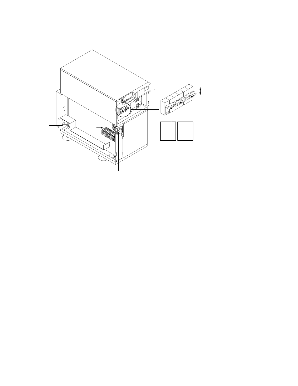
4. Verify that the UPS battery breaker CB1 and optional CB2 are in
the OFF position (see Figure 9).
Terminal
Block
Output
Conduit
Landing
Maintenance
Bypass
Switch
ON
OFF
F1
Battery
Neutral
Fuse
CB1
Internal
Battery
Breaker
CB2
(Optional)
External
Battery
Breaker
Figure 9. Connecting PDM Wiring to Terminal Block
5. Remove the lower rear panel of the UPS by unscrewing the six
screws. Save the screws for reuse; the panel is no longer needed
(see Figure 10).
6. Mount the PDM chassis in the spot previously occupied by the
rear panel. The wires exiting the PDM should be close to the
output conduit landing on the UPS (see Figure 10).
See also other documents in the category Powerware Tools:
- 5110 (14 pages)
- UPS 1000 - 2200 (24 pages)
- 9 (70 pages)
- 9155 UPS20-30kVA (52 pages)
- 8 - 15 kVA (46 pages)
- 9125 Two-in-One UPS 5000 (66 pages)
- Model V-2000B (137 pages)
- 9335 (100 pages)
- 9120 (5 pages)
- 5115RM (24 pages)
- P93 (6 pages)
- 9390 UPS 100160 kVA (216 pages)
- Horsepower Computer System ST-2400S (17 pages)
- 9155 (10 pages)
- 9125 Two-in-One UPS 2500 (78 pages)
- 5075 kVA (162 pages)
- 380/220V (72 pages)
- 30-160kVA (48 pages)
- Ferrups FE/QFE 500VA (76 pages)
- FSS-0342J (44 pages)
- 9395 UPS and Plus 1 UPS 650825 kVA (192 pages)
- 9315s (205 pages)
- Ferrups FE/QFE UPS (72 pages)
- 9315 UPS (84 pages)
- 5140 (68 pages)
- 9330 (246 pages)
- 9355 (62 pages)
- BladeUPS none (32 pages)
- 5115A USB (44 pages)
- 9170+ (12 pages)
- 9170+ (94 pages)
- 9910 p Series (6 pages)
- 9125 (30 pages)
- 4500 (92 pages)
- 9395 (4 pages)
- X-Slot USB Module (10 pages)
- 5105 (4 pages)