Powerware 9150 User Manual
Page 35
Installation
31
Powerware
®
9150 User’s Guide
:
www.powerware.com
CB2
CB1
Safety
Wire
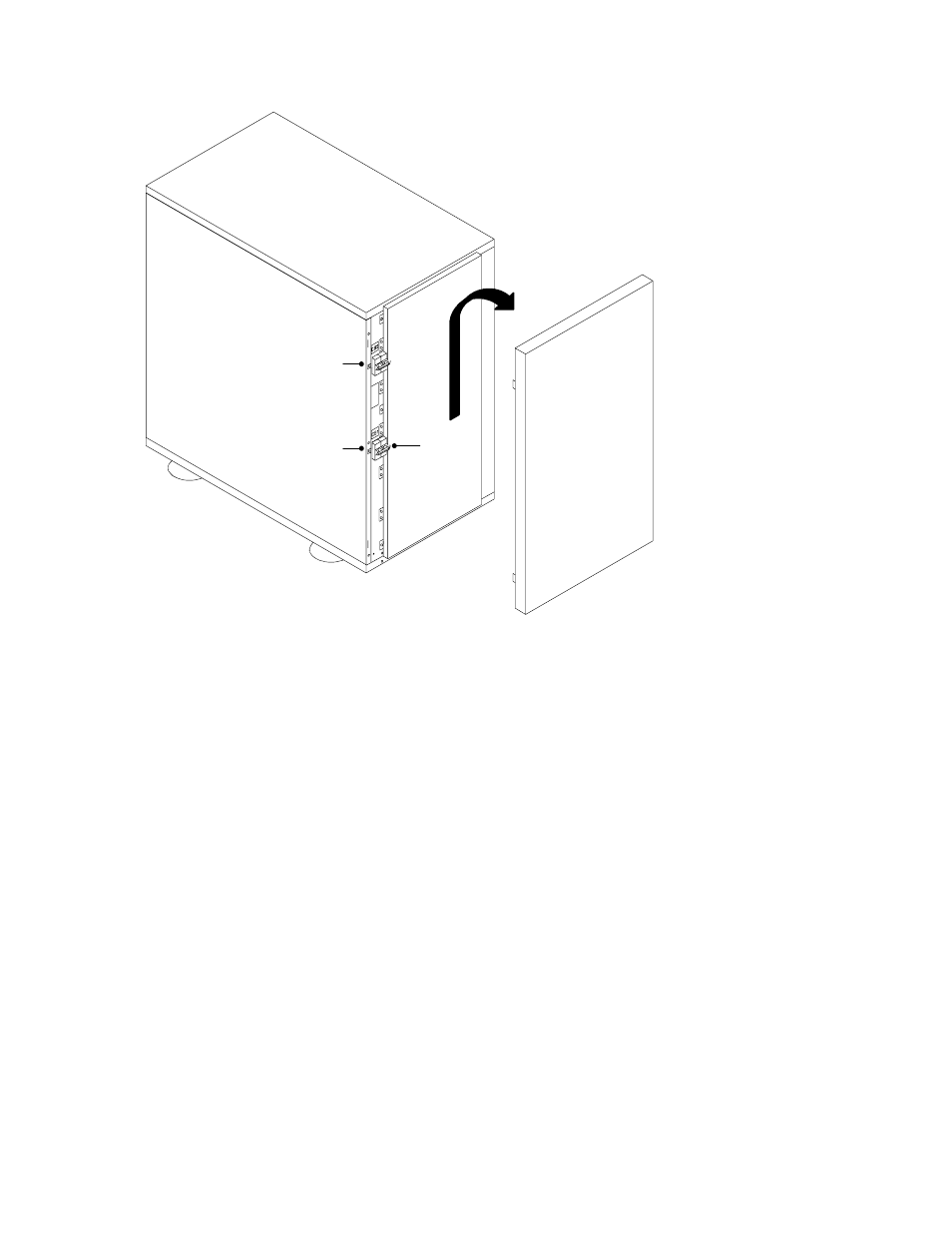
Figure 12. EBC Front Panel
5. Verify that the circuit breakers CB1 and CB2 are in the OFF
position on each battery cabinet.
6. Remove the cover plate on the rear of the UPS cabinet (see
Figure 13). Pull the battery connector out of the UPS, cut the
tie-wrap, and discard the cover plate.
Pull the battery cable from the rear of the battery cabinet and
plug it into the battery connector on the UPS rear panel. Rotate
the EBC conduit fitting into position (90
angle up).
Push the battery cable into the UPS and secure the EBC cover
plate to the UPS rear panel.
See also other documents in the category Powerware Tools:
- 5110 (14 pages)
- UPS 1000 - 2200 (24 pages)
- 9 (70 pages)
- 9155 UPS20-30kVA (52 pages)
- 8 - 15 kVA (46 pages)
- 9125 Two-in-One UPS 5000 (66 pages)
- Model V-2000B (137 pages)
- 9335 (100 pages)
- 5115RM (24 pages)
- 9120 (5 pages)
- P93 (6 pages)
- 9390 UPS 100160 kVA (216 pages)
- Horsepower Computer System ST-2400S (17 pages)
- 9155 (10 pages)
- 9125 Two-in-One UPS 2500 (78 pages)
- 5075 kVA (162 pages)
- 380/220V (72 pages)
- 30-160kVA (48 pages)
- Ferrups FE/QFE 500VA (76 pages)
- FSS-0342J (44 pages)
- 9395 UPS and Plus 1 UPS 650825 kVA (192 pages)
- 9315s (205 pages)
- Ferrups FE/QFE UPS (72 pages)
- 9315 UPS (84 pages)
- 5140 (68 pages)
- 9330 (246 pages)
- 9355 (62 pages)
- BladeUPS none (32 pages)
- 5115A USB (44 pages)
- 9170+ (12 pages)
- 9170+ (94 pages)
- 9910 p Series (6 pages)
- 9125 (30 pages)
- 4500 (92 pages)
- 9395 (4 pages)
- X-Slot USB Module (10 pages)
- 5105 (4 pages)