Powerware 9150 User Manual
Page 32
Installation
28
Powerware
®
9150 User’s Guide
:
www.powerware.com
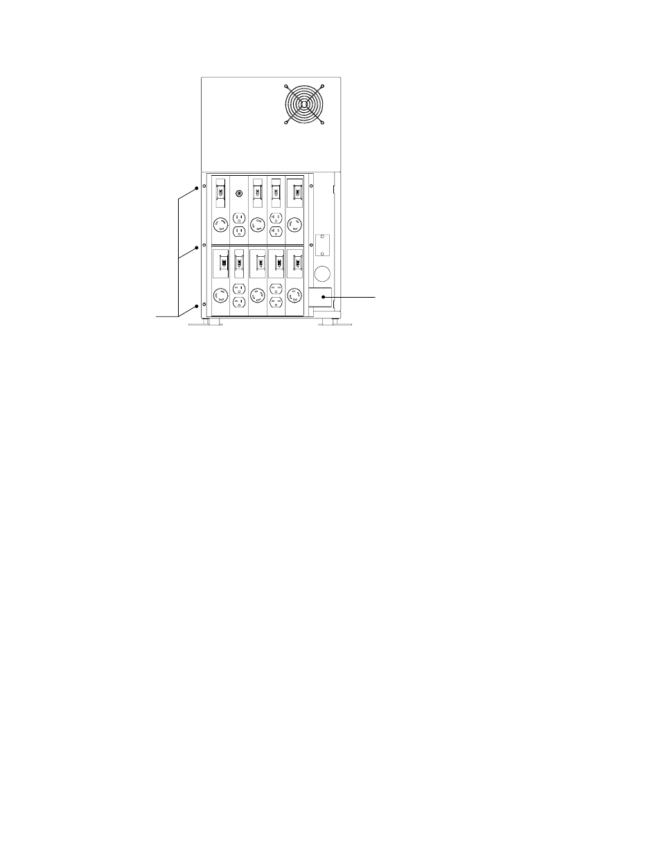
Screws from
UPS panel; 3 on
each side
reused for PDM
Wire Cover for
Output Conduit
Landing
Figure 10. Mounting the PDM to UPS Rear Panel
7. Insert the bushing (provided with the PDM packaging) into the
output conduit landing.
8. Hardwire the input (TB1-1 through TB1-4) terminations for the
UPS. See the following hardwired terminations table for
specifications. See Figure 11 for a detailed view of the terminal
blocks.
9. Insert the wires from the PDM into the output conduit landing
and connect to the UPS terminal block according to the
following table.
See also other documents in the category Powerware Tools:
- 5110 (14 pages)
- UPS 1000 - 2200 (24 pages)
- 9 (70 pages)
- 9155 UPS20-30kVA (52 pages)
- 8 - 15 kVA (46 pages)
- 9125 Two-in-One UPS 5000 (66 pages)
- Model V-2000B (137 pages)
- 9335 (100 pages)
- 9120 (5 pages)
- 5115RM (24 pages)
- P93 (6 pages)
- 9390 UPS 100160 kVA (216 pages)
- Horsepower Computer System ST-2400S (17 pages)
- 9155 (10 pages)
- 9125 Two-in-One UPS 2500 (78 pages)
- 5075 kVA (162 pages)
- 380/220V (72 pages)
- 30-160kVA (48 pages)
- Ferrups FE/QFE 500VA (76 pages)
- FSS-0342J (44 pages)
- 9395 UPS and Plus 1 UPS 650825 kVA (192 pages)
- 9315s (205 pages)
- Ferrups FE/QFE UPS (72 pages)
- 9315 UPS (84 pages)
- 5140 (68 pages)
- 9330 (246 pages)
- 9355 (62 pages)
- BladeUPS none (32 pages)
- 5115A USB (44 pages)
- 9170+ (12 pages)
- 9170+ (94 pages)
- 9910 p Series (6 pages)
- 9125 (30 pages)
- 4500 (92 pages)
- 9395 (4 pages)
- X-Slot USB Module (10 pages)
- 5105 (4 pages)