Ups setup, Floor loading – Powerware 9150 User Manual
Page 22
Installation
18
Powerware
®
9150 User’s Guide
:
www.powerware.com
UPS Setup
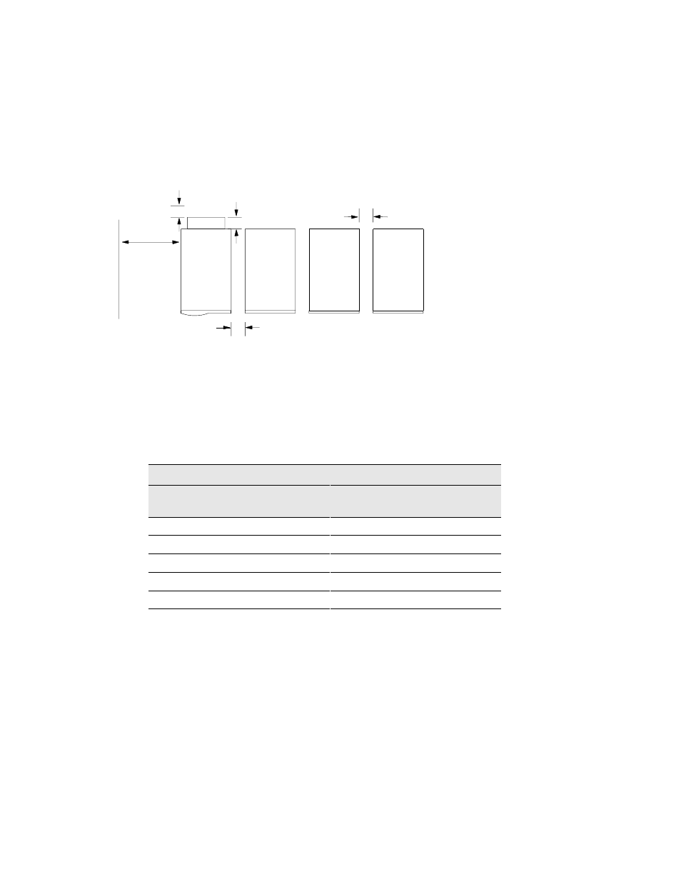
When the UPS is in use, allow a minimum of 4 inches (100 mm) for
ventilation on both sides, top, and rear of the UPS (see Figure 3). When
the UPS is serviced, allow 30 inches (762 mm) for removal of the UPS
left panel. Maintain clearance in front of the UPS for user operations. If
you have an optional Power Distribution Module (PDM), allow
additional space in the rear for the PDM cord connections.
4
2 Minimum Spacing
Around UPS
30
2
Clearance
for Service
UPS
EBC
EBC
EBC
PDM
5.0
2 PDM Depth
PDM Cord Connections
3
2 Minimum Spacing
Around EBC
Figure 3. Spacing Requirements (Top View)
Floor Loading
When planning the installation, consider the UPS weight for floor
loading. The strength of the installation surface must be adequate for
point and distributed loadings. The weights are shown in the following
table.
Standard Model Floor Loadings
Powerware 9150
Maximum
Weight (lb)
Point Loading
(lb/in
2
)
Distributed
Loading (lb/ft
2
)
Model 8 kVA
550
12.5
170
Model 10 kVA
550
12.5
170
Model 12.5 kVA
550
12.5
170
EBC-48
468
9.6
130
EBC-96
765
17.4
236