Paradyne COMSPHERE 3000 User Manual
Page 90
COMSPHERE Interface Connections
A-9
3000-A2-GA31-80
December 1994
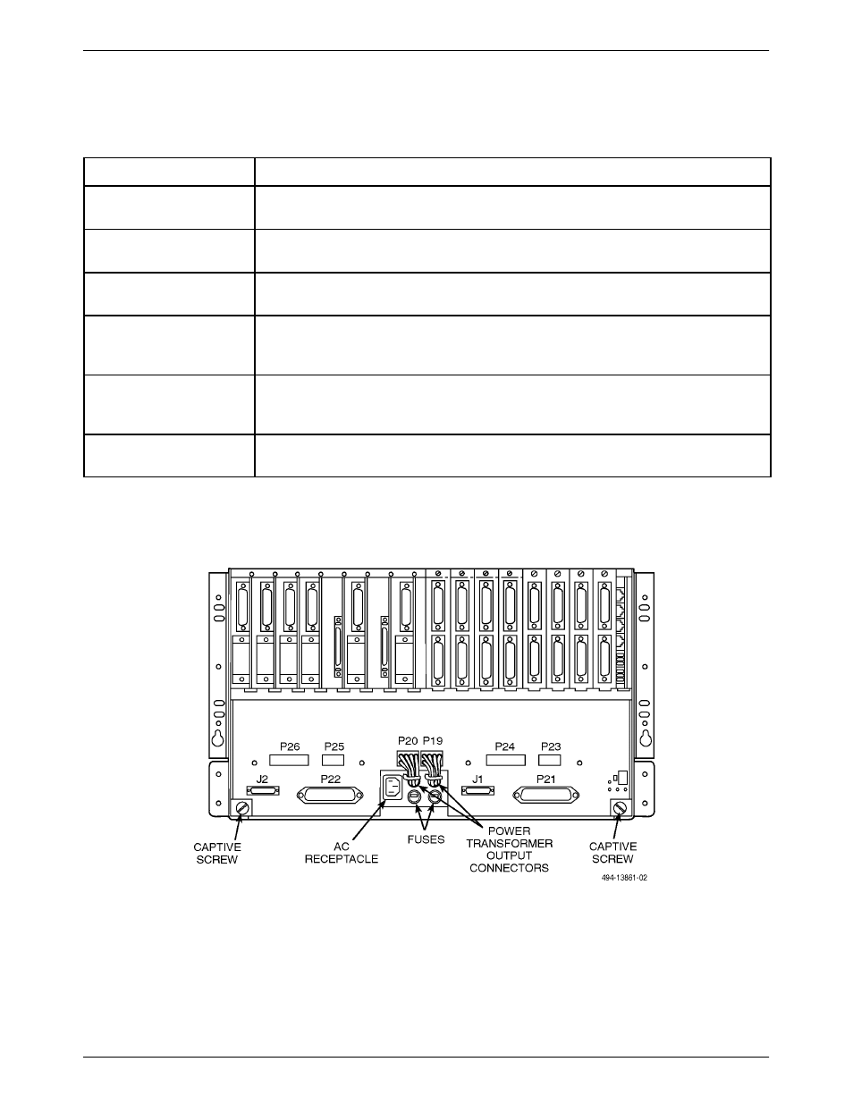
Table A-11
Connectors on the COMSPHERE 3000 Series Carrier’s Backplane
Connectors
Function
P19, P20
These connectors supply low voltage ac or low voltage dc from the power supply
unit onto the COMSPHERE 3000 Series Carrier’s backplane.
P21
This 50-pin connector provides the digital or 4-wire and 2-wire leased-line
interface for DCEs (DSUs and dial/lease modems) in Slots 1 through 8.
P22
This 50-pin connector provides the digital or 4-wire and 2-wire leased-line
interface for DCEs (DSUs and dial/lease modems) in Slots 9 through 16.
P23, P24
These connectors are used by the Network Interface Modules (NIMs) to provide
the dial interface through a 50-pin connector for dial/lease modems in Slots 1
through 8.
P25, P26
These connectors are used by the Network Interface Modules (NIMs) to provide
the dial interface through a 50-pin connector for dial/lease modems in Slots 9
through 16.
J1
This 26-pin high-density D-type connector provides the D-lead control interface
for dial/lease modems in Slots 1 through 8.
Figure A-3. Connectors on the COMSPHERE 3000 Series Carrier Backplane