Modular dsu-tdm or dsu-mcmp and connector module – Paradyne COMSPHERE 3000 User Manual
Page 75
COMSPHERE 3000 Series Carrier
3-48
December 1994
3000-A2-GA31-80
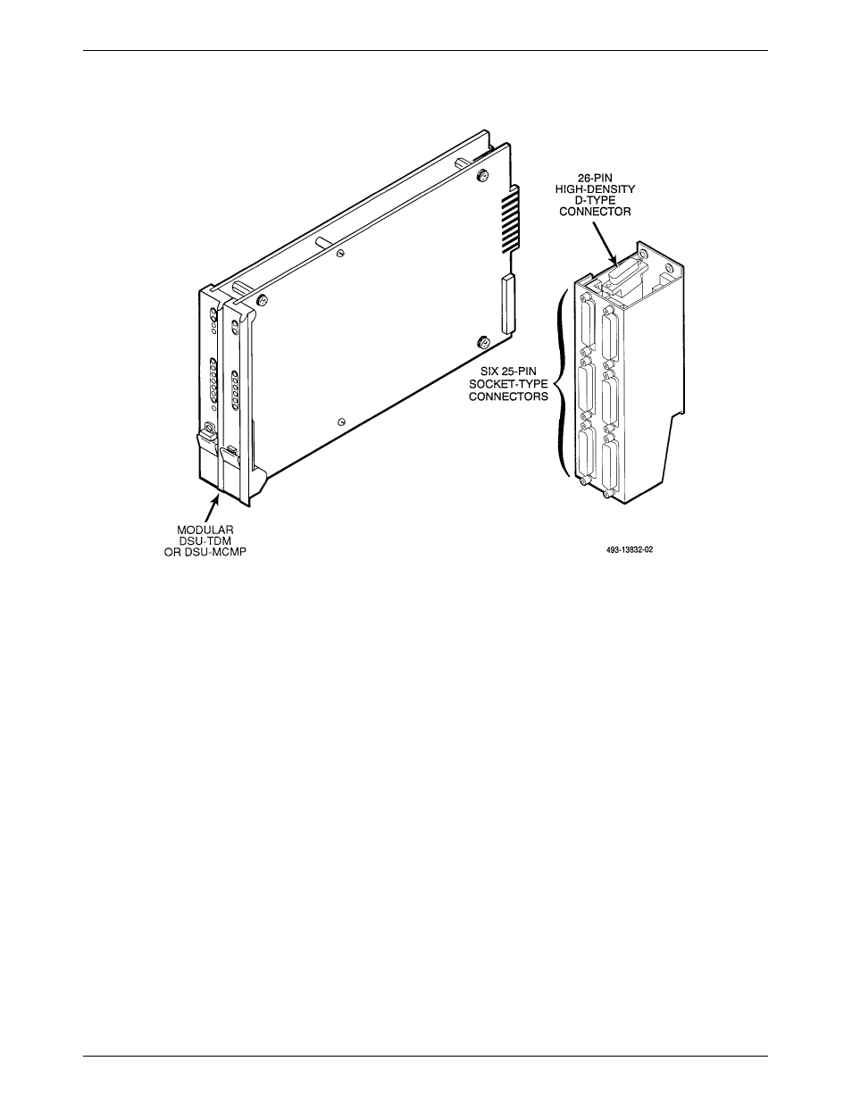
Figure 3-35. Modular DSU-TDM or DSU-MCMP and Connector Module
Connector modules have six ports (labeled Port 1
through Port 6). Each port is a 25-pin connector which
provides the EIA-232 DTE interface. In addition, a 26-pin
high-density D-type connector is located at the top of the
connector module and provides the V.35 interface for
either Port 1 or an aggregate data path. This connector
requires a 6-port V.35 interconnect cable (supplied by the
customer), which converts the 26-pin high-density D-type
interface to the standard 34-pin V.35 interface. Connector
modules allow removal of a modular DSU-TDM or
DSU-MCMP circuit card without disconnecting the DTE
cables.
When non-modular DSUs are installed in the same
carrier with non-modular dial/lease modems, group
dial/lease modems together and install them starting from
the left (in Slot 1) before installing the DSUs. However, if
modular circuit cards are installed in the same carrier as
non-modular circuit cards, the modular circuit cards must
be installed to the left of all other devices in the carrier.
Before you install Model 3151 CSUs or Model 3161
DSU/CSUs in a carrier, you must first install an Auxiliary
Backplane, as described in the Auxiliary Backplane
Installation section earlier in this chapter. Figure 3-36
shows the Models 3151 and 3161 circuit cards.
The next five sections contain the following
information:
•
Preinstallation information.
•
Procedure for installing modular circuit cards and
DTE connectors (rear connector plates and
connector modules).
•
Procedure for installing non-modular circuit cards.
•
Procedure for installing 3151 and 3161 circuit
cards.
•
Procedure for installing filler panels.