Shared diagnostic control panel, Fan module cooling requirements, Shared diagnostic control panel status indicators – Paradyne COMSPHERE 3000 User Manual
Page 44
Installation
3-17
3000-A2-GA31-80
December 1994
Shared Diagnostic Control
Panel (SDCP) Installation
A single Shared Diagnostic Control Panel (SDCP) can
control up to eight carriers containing up to 128
compatible T1 CSUs, T1 DSU/CSUs, DSUs, or dial/lease
modems. The number of devices that can be installed in a
carrier or cabinet is reduced when Time Division
Multiplexer (TDM) or Multichannel Multipoint (MCMP)
circuit cards are also installed. A TDM or MCMP circuit
card (functioning as a multiplexer or digital bridge) is
physically attached to Models 3551, 3611, and 3616
DSUs and occupies a separate slot in the carrier. In a
single carrier without an NMS connection, an SDU is not
required to provide the SDCP interface. In a cabinet
configuration of two or more carriers, however, an SDU is
required in each carrier to connect the SDCP interface
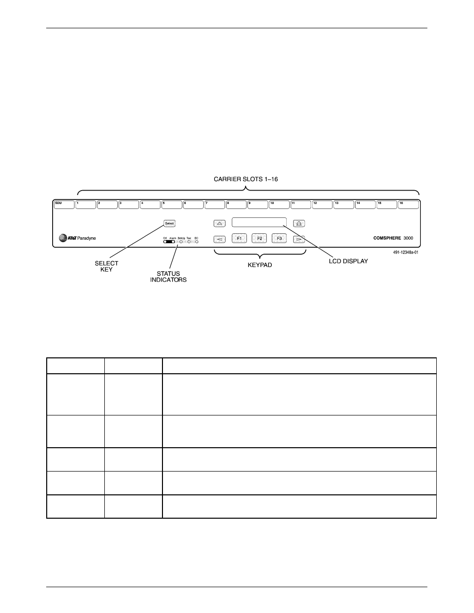
from carrier to carrier. Figure 3-11 shows the SDCP and
Table 3-2 defines the SDCP status indicators.
Figure 3-11. Shared Diagnostic Control Panel
Table 3-2
Shared Diagnostic Control Panel Status Indicators
Label
Color
Description
OK
green
Health and status indicator for the selected
3151/3161/3551/3611/3616/3811/3911; mirrors the OK indicator on the
3151/3161/3551/3611/3616/3811/3911 faceplate and the power indicator on
the 3811/3911.
Alarm
red
Health and status indicator for the selected
3151/3161/3551/3611/3616/3811/3911; mirrors the Alrm indicator on the
3151/3161/3551/3611/3616/3811/3911.
BckUp
yellow
Mirrors the Dial indicator on the selected 3551/3611/3616/3811/3911. Not
used for the 3151/3161.
Test
yellow
Mirrors the Test indicator on the selected
3151/3161/3551/3611/3616/3811/3911.
EC
green
Error Correction indicator for use by 3811/3911 modems. Not used for the
3151/3161/3611/3616.