T1 network cable retainer – Paradyne COMSPHERE 3000 User Manual
Page 61
COMSPHERE 3000 Series Carrier
3-34
December 1994
3000-A2-GA31-80
You need a Phillips screwdriver to install the Auxiliary
Backplane. Long-nose pliers, a 1/4
″
nut driver, and a
5/16
″
nut driver are also required.
WARNING
Turn off the power to the 3000
Series Carrier before you
install the Auxiliary Backplane.
To install the Auxiliary Backplane (Figure 3-24):
.
Procedure
1. Remove the power transformer unit from the front
of the 3000 Series Carrier.
2. Remove the NIM, if present, from the back of the
3000 Series Carrier.
3. If the carrier is already installed in a cabinet with
equipment located below, place a cardboard or
paper pad from the front perpendicular to the main
backplane at the bottom of the carrier to catch any
hardware that may fall below.
4. Use a 1/4
″
nut driver to remove the two metal
hexagonal standoffs on either side of connectors
P23 and P24, if mounting the Auxiliary Backplane
on the right side, or P25 and P26 if mounting the
backplane on the left. Refer to Figure 3-7.
5. Insert the custom hexagonal standoffs into the
existing standoff holes from the rear, then use the
long-nose pliers and a 5/16
″
nut driver to install
the nylon insulating washers and No. 5 nuts from
the front of the carrier.
6. Tighten the nuts with the 5/16
″
and 1/4
″
nut
drivers.
7. Determine which screw holes you need to use to
mount the Auxiliary Backplane using the six
screws provided.
The backplane has pointer symbols next to the
center and bottom rows of screw holes (refer to
the Figure 3-24). If you are mounting the
backplane on the right side of the rear of the
carrier, use the two screw holes with the pointers
facing to the right. If mounting the backplane on
the left side, use the holes with the pointers facing
left.
For the top row, use the same screw holes for
mounting on either side.
8. Align the backplane using the custom standoffs at
the bottom and the corresponding holes on the
bottom row of the backplane.
9. Insert and finger-tighten the two bottom row
screws (3/4
″
length). If you are mounting the
backplane on the left side, you must insert the
small 3/8
″
screw into the open slot at the lower
left side of the backplane.
10. Insert and finger-tighten the two top row screws
(1
″
length).
11. Insert and finger-tighten the two center row
screws (1
″
length).
12. Using a screwdriver, tighten all the screws. Be
careful not to use excessive force.
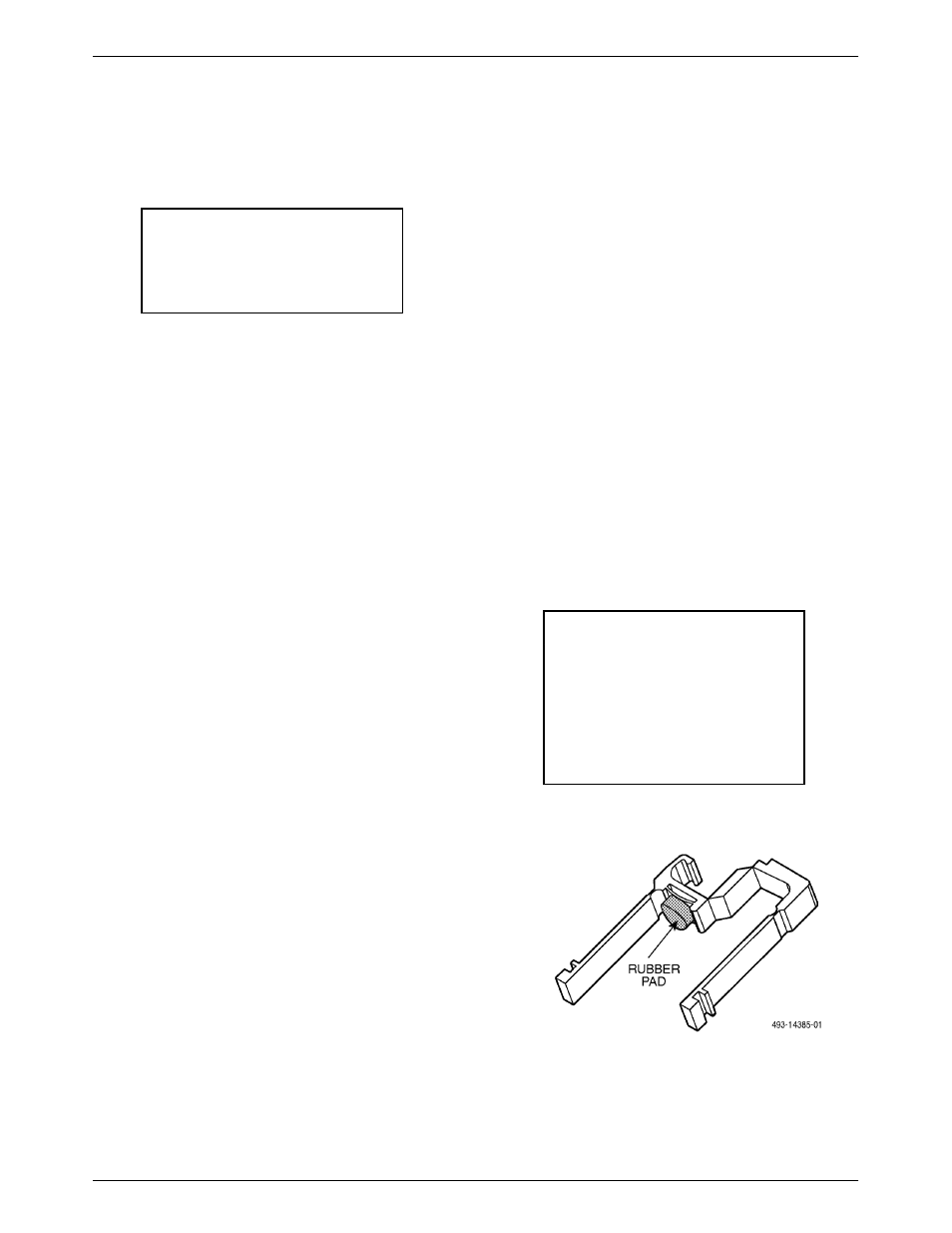
13. Ensure that the rubber pad is properly attached to
the black plastic T1 network cable retainer
(Figure 3-23).
This plastic cable retainer secures the T1
connecting cable once it is plugged in.
NOTE
Do not install the cable retainer if
you will be installing a Telco
connector cable with a straight
cable entry. Instead, secure this
cable using the screw lock
provided on each side of the T1
network connector.
Figure 3-23. T1 Network Cable Retainer