Comsphere 3000 series carrier (rear), Power transformer unit installation – Paradyne COMSPHERE 3000 User Manual
Page 38
Installation
3-11
3000-A2-GA31-80
December 1994
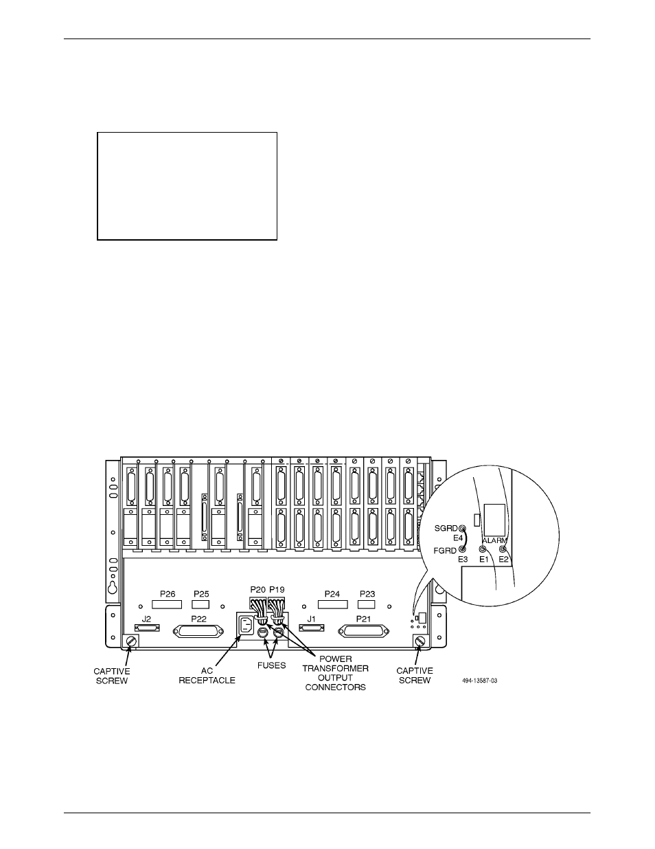
4. At the rear of the carrier (Figure 3-7), disconnect
the ac power cord from the carrier.
NOTE
Removing power causes loss of
service to all 16 circuit card slots
in the carrier. It is therefore
recommended that this
procedure not be performed
during peak operating hours.
5. If this is a new installation, proceed to Step 6. If
the carrier has already been installed, you must
remove the fan module (if installed) and the power
transformer unit:
a. At the rear of the carrier, unscrew the two
captive screws securing the power unit.
Disconnect the two power connectors (P19
and P20) by pressing the catch on the bottom
of each and pull it free of its mating connector.
b. At the front of the carrier, slide the power
transformer unit straight out and set it aside.
You may need another person standing at the
rear to feed the transformer output wires
through the opening in the backplane.
6. Attach either end of the 16-pin ribbon cable
(delivered with the SDCP) to its connector on the
carrier backplane. Feed the ribbon cable through
the four built-in retainer clips provided in the
carrier, then proceed to install the power
transformer unit.
Power Transformer Unit Installation
To mount the power transformer unit in the carrier:
.
Procedure
1. If the SDCP ribbon cable has been installed,
proceed to Step 2.
Remove the cover plate by unscrewing the four
captive screws at the front of the carrier.
2. At the front of the carrier, place the power
transformer unit on the flanges at the bottom of
the carrier (Figure 3-6). Slide the power
transformer unit into place against the rear rail of
the enclosure, guiding the transformer output
wires through the opening in the backplane.
Figure 3-7. COMSPHERE 3000 Series Carrier (Rear)