Paradyne COMSPHERE 3000 User Manual
Page 73
COMSPHERE 3000 Series Carrier
3-46
December 1994
3000-A2-GA31-80
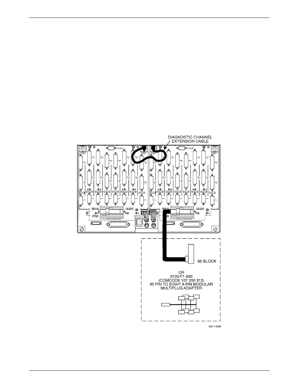
Depending on your configuration, use one of the
following schemes for the Models 3151 and 3161 network
interface (Figure 3-33).
•
The 50-pin cable can be attached to a
66A-punchdown block. With this scheme, the
circuits must be hard-wired to the block.
•
The 50-pin cable can be plugged into a
3100-F1-930 adapter cable. This adapter cable
provides 8 non-keyed modular plugs using Pins 1,
2, 4, and 5. These connect the T1 CSU or T1
DSU/CSU to a standard DDS network interface
(RJ48C) and provide the new JM8-style leased-line
connection for the T1 interface.
To install the Models 3151 and 3161 network interface:
.
Procedure
1. Connect the network cable to the carrier.
2. If you are using the Telco connector cable, install
the black plastic network cable retainer. If you are
using a straight-in connector, use a small
screwdriver to engage and tighten the screws.
3. Connect the individual cables with 8-pin modular
plugs into the adapter for each T1 line.
Figure 3-33. Network Interface for Models 3151 and 3161 Using an Auxiliary Backplane