Ddc instructions – Philips V30 User Manual
Page 22
X
Go to cover page
22
107T5
DDC Instructions
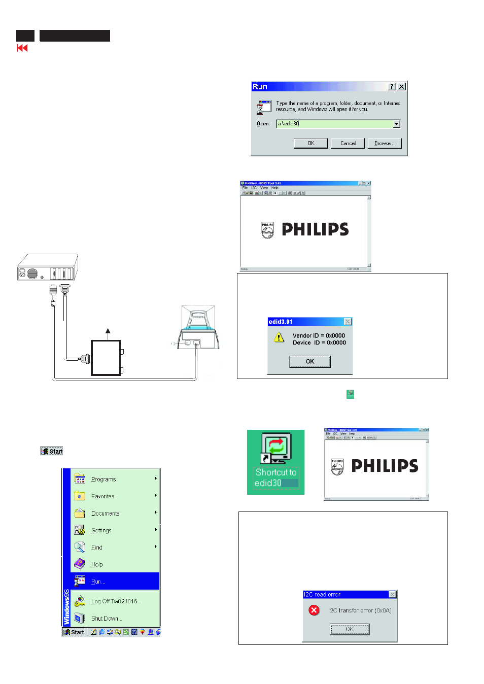
4. Configuration and procedure
There is no Hardware DDC (DDC IC) anymore. Main EEPROM stores
all factory settings and DDC data (EDID code) which is so called
Software DDC. The following section describes the connection and
procedure for Software DDC application. The main EEPROM can be re-
probrammed by enabling "factory memory data write" function on the
DDC program (EDID301.EXE).
Step 3: Installation of EDID301.EXE
Method 1: Start on DDC program
Start Microsoft Windows.
1. Insert the disk containing EDID301.EXE program into floppy disk
drive.
2. Click
, choose Run at start menu of Windows 95/98 as
shown in Fig. 4.
Fig. 4
*** INITIALIZE ALIGNMENT BOX ***
In order to avoid that monitor entering power saving mode due to
sync will cut off by alignment box, it is necessary to initialize
alignment box before re-programming DDC Data. Following steps
show you the procedures and connection.
Step 1
Step 2
: Supply 8~12V DC power source to the Alignment box by
plugging a DC power cord or using batteries.
: Connecting printer cable and video cable of monitor as
shown in Fig.3.
4. Click
button. The main menu appears (as shown in Fig. 6).
OK
This is for initialize alignment box.
Fig. 6
Fig. 5
Fig. 7
Note 1: If the connection is improper, you will see the following error
message (as shown in Fig. 7) before entering the main menu.
Meanwhile, the (read EDID) function will be disable. At this time,
please make sure all cables are connected correctly and fixedly,
and the procedure has been performed properly.
3. At the submenu, type the letter of your computer's floppy disk drive
followed by :EDID301 (for example, A:\EDID301, as shown in Fig. 5).
Method 2: After create a shortcut of EDID301.EXE
This is for initialize alignment box.
: Double click EDID301 icon
(as shown in Fig. 8) which is
on the screen of Windows Wallpaper.
Bring up main menu of EDID301 as shown in Fig. 9.
Fig. 9
Note 2: During the loading, EDID301 will verify the EDID data which just
loaded from monitor before proceed any further function, once
the data structure of EDID can not be recognized, the following
error message will appear on the screen as below. Please
confirm following steps to avoid this message.
1. The data structure of EDID was incorrect.
2. DDC IC that you are trying to load data is empty.
3. Wrong communication channel has set at configuration setup
windows.
4. Cables loosed or poor contact of connection.
Fig. 8
1
Fig. 3
Rear view of the monitor
~
~
PC
T
o
printer
port
(L
TP1)
DC Power
8~12 V
Printer
Port
T
o
video
card
To
Monitor
To PC
Video cable