Mechanical instructions – Philips V30 User Manual
Page 15
9
Go to cover page
15
Mechanical Instructions
0. General
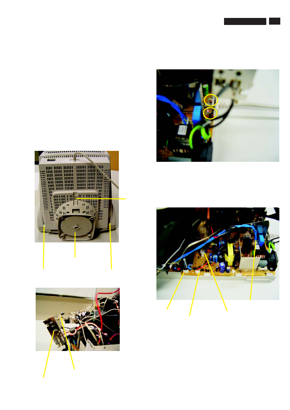
2. Video panel
3.Main board connector in Fig. 4
To be able to perform measurements and repairs on the "circuit
boards", these unit should placed in the service position first.
-Remove 2 screws as shown
-Remove back cover as shown
-Remove pedestal as shown
-Disconnect york wire
-Disconnect rotation connector
-Disconnect control board connector
-Remove Screw for fixed I/F cable
-Remove signal connector
-Remove degaussing wire connector
1.Remove the rear cover in Fig. 1.
- Disconnect the wire between metal shield of Video panel and
CRT neck as shown in Fig. 2.
- Disconnect the CRT ground from Video panel.
- Remove screw grounding and grounding wire in Fig. 3.
Fig. 1
Screw
Screw
Pedestal ass'y
Video Panel
CRT grouding wirel
Fig. 2
Clip
Fig. 3
Fig. 4
screw - grounding
Control connector
Signal connector
Degaussing wire connector
Rotation connector
===============>
107T5
- 150B (22 pages)
- 220SW9FS (118 pages)
- 1.09E+52 (2 pages)
- 109S (108 pages)
- 107P50 (2 pages)
- 150b5 (87 pages)
- 109B4x (2 pages)
- 107G (94 pages)
- 109B60 (2 pages)
- 150B3M/150B3Q (89 pages)
- 107T60 (2 pages)
- 107T70 (3 pages)
- 220VW8 (92 pages)
- 220VW8 (86 pages)
- 220VW8 (60 pages)
- 200WS8 (89 pages)
- 190C6 (95 pages)
- SVGA/EVGA 15C04204 (16 pages)
- 107B75 (2 pages)
- 107S76 (3 pages)
- VSS9451 (6 pages)
- 150B6CG (2 pages)
- 109B72 (3 pages)
- 107E69 (46 pages)
- 109E51 (2 pages)
- 104S19 (2 pages)
- 107E (123 pages)
- 107S4 (101 pages)
- 150E6 (70 pages)
- 107E71/00 (2 pages)
- 107H62 (2 pages)
- 107S63 (46 pages)
- 107T40 (2 pages)
- 190C8 (112 pages)
- 190C8 (118 pages)
- 200XW7 (109 pages)
- 190TW8 (19 pages)
- 107X2 (145 pages)
- 150C5BS (2 pages)
- 107B5 (137 pages)
- 105E (56 pages)
- 105E (54 pages)
- 150B (81 pages)
- 150P2M (89 pages)
- 170X6 (97 pages)