Patton electronic 3088 Series User Manual
Page 21
Introduction
21
Model 3088 Series User Manual
2 • Configuration
Line Code
(models K & T)
Selects line coding for the T1 or E1 line.
AMI
HDB3 (E1 only)
B8ZS (T1 only)
Line Build Out
(models K & T)
Selects wave form used on the T1 or E1 line.
Pulse–75 Ohm(E1)
Pulse–120 Ohm (E1)
0.0 dB (T1)
-7.5 dB (T1)
-15.0 dB (T1)
-22.5 dB (T1)
RX Equalizer
(models K & T)
When enabled, this feature removes signal distortion introduced on
the T1 or E1 cable.
Enabled (select for
long–haul link).
Disabled (select for
short–haul link). Long
haul LBO (line build-
out) is defined by
ANSI T1.403).
Pass Framing
(models K & T)
When enabled, the RocketLink-G transparently passes framing infor-
mation (T1 F-bit or E1 TS0) over the DSL link to the remote T1/E1 net-
work.
Enabled or Disabled.
Must always be
enabled for T1.
Pass Alarms
(models K & T)
When enabled, the RocketLink-G passes alarms detected on one T1/
E1 network over the DSL link to the remote T1/E1 network.
Enabled or Disabled
Clock Mode
Defines the clock source operation for both DSL and serial/T1/E1
ports as follows. Internal: the on–board oscillator in the 3088 pro-
vides clock for both serial/T1/E1 and DSL lines. External: the
serial/T1/E1interface provides clock for the DSL line. Receive
Recover: the DSL interface provides clock for the serial/T1/
E1 line.
Internal
External
Receive Recover
Annex
The G.991.2 Annex.
A or B
Line Probe
When this special Patton feature is enabled, the 3088 will set the
DSL data rate to the best rate in the 3–36 timeslot range that both
NTUs can support. Enable for rate adaptive applications.
Enabled or Disabled
Loopback
The 3088 provides both a local loopback (LAL) and a remote
loopback (RDL). This can be used to troubleshoot problems.
OFF, LAL, or RDL
Pattern
The 3088 provides an internal PRBS pattern generator and detec-
tor that can be used to run BER tests without external equipment.
The patterns offered are 511 and 511 with errors.
OFF, 511, or 511E
DSL Error Monitor
Maximum Intervals
The number of errors allowed in an interval before considering
the interval errored. A value of 0 disables the error monitor.
0–255
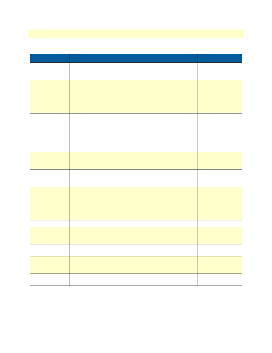
Table 2. RocketLink-G configurable parameters (Continued)
Parameter
Description
Possible Values