Troubleshooting & repair – Lincoln Electric PIPELINER 200 User Manual
Page 123
MAIN GENERATOR FRAME REMOVAL AND REPLACEMENT PROCEDURE
(CONTINUED)
TROUBLESHOOTING & REPAIR
F-53
F-53
PIPELINER® 200
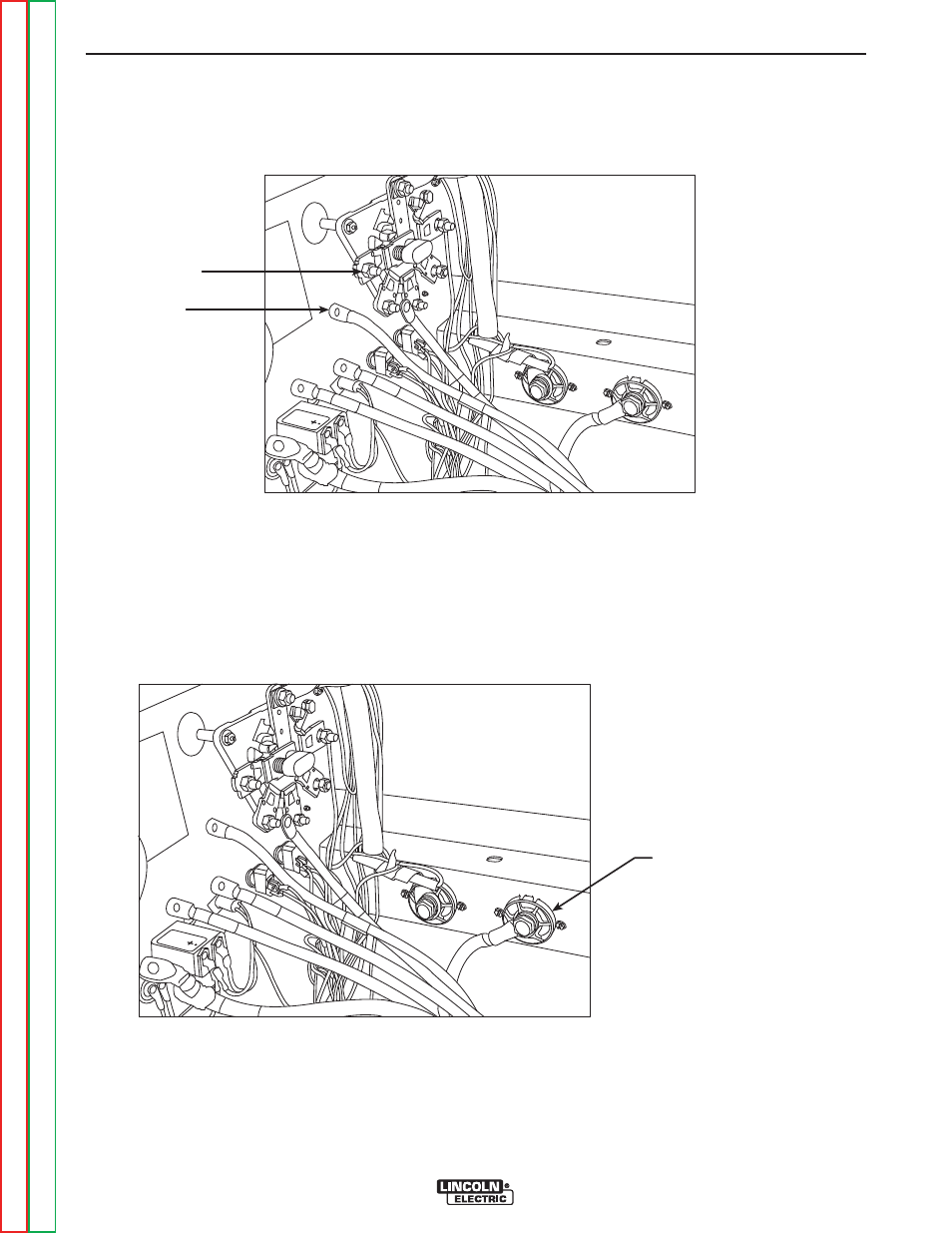
FIGURE F.19 – SELECTOR SWITCH LEAD REMOVAL
SELECTOR
SWITCH
TERMINAL
LEAD (5)
A
C
B
D
E
9. Using the 1/2” wrench, remove the five heavy
flex leads from the selector switch terminals.
Label the leads for reassembly. See Figure
F.19.
FIGURE F.20 – OUTPUT TERMINAL LEAD REMOVAL
POSITIVE OUTPUT
TERMINAL AND LEAD
A
C
B
D
E
10. Using the 3/4” wrench, remove the copper
strap from the negative output terminal. See
Figure F.20.
11. Using the 3/4” wrench, remove the heavy
lead from the positive output terminal. See
Figure F. 20.
See also other documents in the category Lincoln Electric Tools:
- AIR VANTAGE IM10065 (54 pages)
- PRECISION TIG IM936 (44 pages)
- MAGNUM IM887 (20 pages)
- X-Tractor 1GC (4 pages)
- CAN-M393 (3 pages)
- CV ADAPTER IM309-D (46 pages)
- Idealarc 250 (2 pages)
- L12810-1 (4 pages)
- IM359-G (34 pages)
- OUTBACK 145 (34 pages)
- 4.1 (20 pages)
- CV-655 (47 pages)
- K1308-12 (4 pages)
- IM803-B (31 pages)
- LN-25 IM10092 (39 pages)
- PRECISION TIG 275 IM702-A (46 pages)
- Pipeliner 200D (4 pages)
- POWER FEED 10M SINGLE/DUAL SVM172-A (151 pages)
- CLASSIC 300G IM659-B (33 pages)
- INVERTEC V350-PRO IM708 (38 pages)
- Magnum 300 and 400 GMA Gun & Cable Assemblies K514 (29 pages)
- CLASSIC III 10061 (34 pages)
- 347 AC-DC (3 pages)
- INVERTEC IM958 (38 pages)
- Cool-Arc 40 (2 pages)
- IM795 (39 pages)
- Excalibur 11018M MR (1 page)
- METALUX 396T8HO (2 pages)
- MIG PAK HD IM822 (39 pages)
- VINTAGE 400 (CE) IM889-A (49 pages)
- IM481-B (35 pages)
- POWER MIG SVM157-A (91 pages)
- 600-I (2 pages)
- 4R90 (8 pages)
- IM613-B (54 pages)
- pmn (35 pages)
- RANGER 250 IM919 (49 pages)
- Welding Helmet (4 pages)
- IM355-C LN-9F GMA (70 pages)
- IM628 (17 pages)
- COOL ARC 35 IM959 (22 pages)
- POWER MIG 215 (35 pages)
- LN-25 PRO IM901-A (44 pages)
- METALUX 248 (2 pages)
- MAGNUM PCT125 (25 pages)