Rear view – Lenovo TS100 User Manual
Page 25
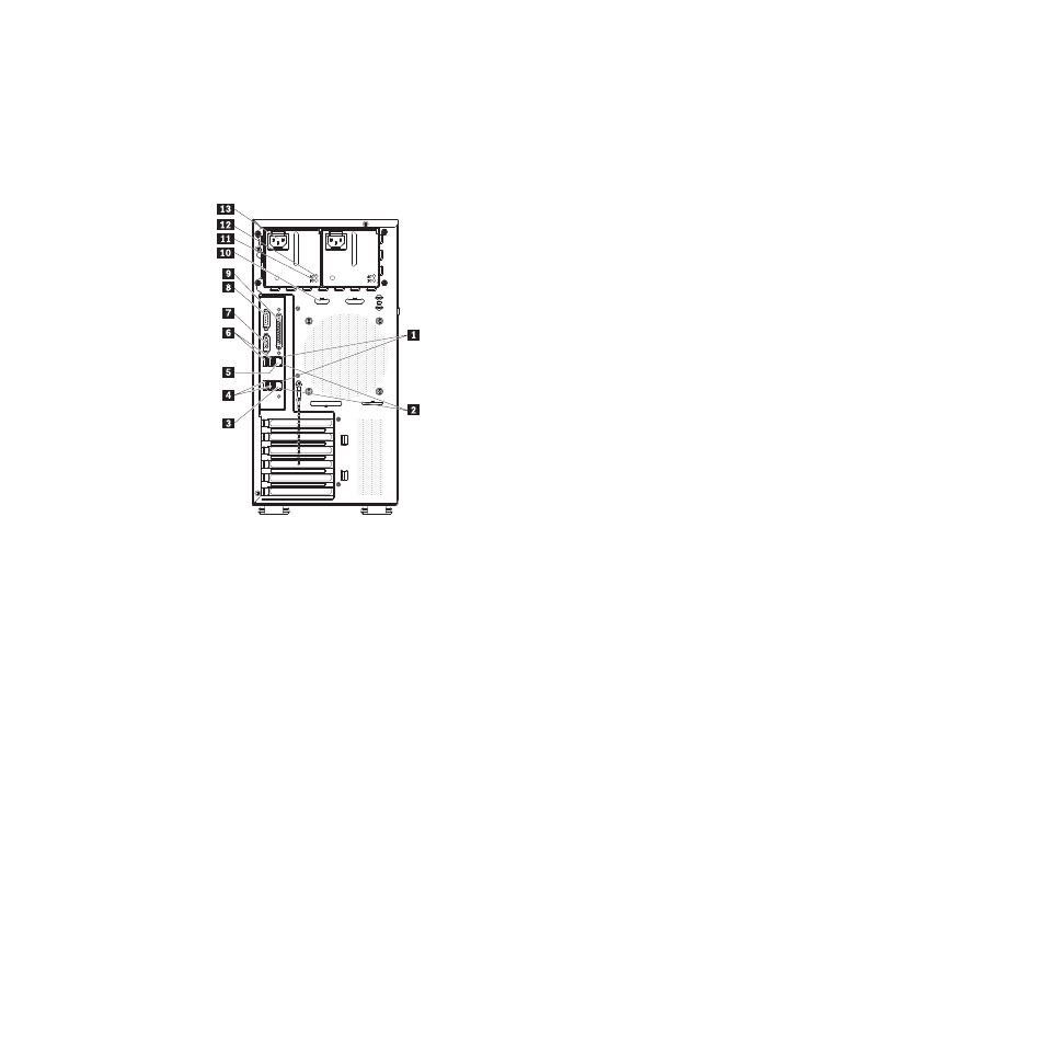
Rear view
The following illustration shows the connectors and LEDs on the rear of the server.
1
Ethernet transmit/ receive activity LED
(amber)
8
Serial 1 (Com1) connector
2
Ethernet link status LED (green)
9
Parallel connector
3
Remote Supervisor Adapter II
SlimLine (Ethernet) connector
10
Serial 2 (Com2) connector
4
USB connectors 1 and 2
11
DC power LED
5
Ethernet connector
12
AC power LED
6
USB connectors 3 and 4
13
Power cord connector
7
Video connector
Power-cord connector
Connect the power cord to this connector.
AC power LED
On some server models, each hot-swap power supply has an ac power
LED and a dc power LED. During typical operation, both the ac and dc
power LEDs are lit.
DC power LED
On some server models, each hot-swap power supply has a dc power LED
and an ac power LED. During typical operation, both the ac and dc power
LEDs are lit.
Serial 2 connector
Connect a 9-pin serial device to this connector.
Parallel connector
Connect a parallel device to this connector.
Serial 1 connector
Connect a 9-pin serial device to this connector.
Chapter 1. Introduction
7