Proper wiring, Augat tool installation, Tracvision a5 wiring diagram – KVH Industries KVH TracVision User Manual
Page 7
Augat Tool
Installation
54-0239
TracVision A5 Shop Manual
© 2004 KVH Industries, Inc., All rights reserved.
• If you must cut the antenna cable, terminate the cable with the
supplied Snap-N-Seal
®
F-connector. Low-quality connectors will
degrade system performance.
• Always use an Augat tool (KVH P/N 19-0242)
to attach F-connectors.
• Do not kink or stress the antenna cable.
• Tighten all connections adequately.
• Use high-quality video cable between receiver and monitor(s).
• Place the RF converter at least 3 feet away from the receiver and
other electronic devices.
Proper Wiring
Effective April 2004
Subject to change without notice
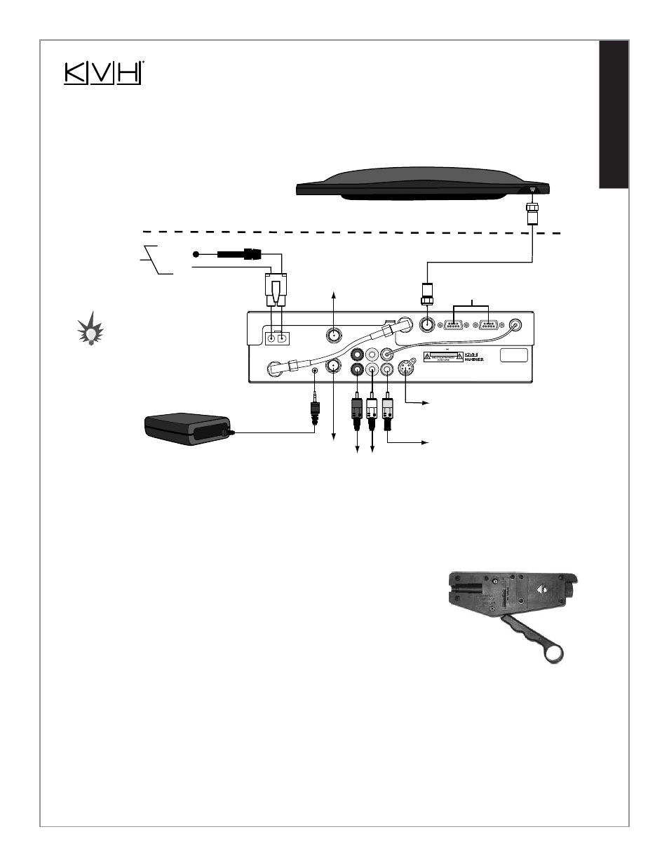
TracVision A5 Wiring Diagram
Antenna
For detailed system wiring
instructions, refer to the
TracVision A5 Installation Guide
.
RF Converter
Receiver
Vehicle Roof
C AU T I O N
KVH® is a registered trademark of KVH Industries, Inc. HUGHES™ is a trademark of Hughes Electronics Corporation.
This device complies with Part 15J of the FCC rules. Operation is subject to the following two conditions:
(1) This device must not cause harmful interference, and (2) This device must accept any interference
received, including interference that may cause undesired operation.
Product Warranty void if outer casing removed.
VEHICLE POWER
(10-16 VDC)
VHF
ANTENNA IN
S-VIDEO
TO KVH
ANTENNA
TO VIDEO
TruSurround, SRS and symbol are trademarks of SRS Labs, Inc.
SATELLITE IN
AUDIO R
AUDIO L
VIDEO
Service/
Maintenance
Only
DC Power
Ground
To Vehicle
Audio
To Vehicle Video
(Option 1)
To Vehicle Video
(Option 1)
To Vehicle Video
(Option 3)
To Vehicle Video
(Option 2)
To VHF Antenna
(Optional)
Vehicle Power
(10-16 VDC)
Fuse
RF REMOTE
INPUT
OUT TO TV
COMPOSITE VIDEO
TO IRD
SATELLITE IN
DIAGNOSTIC PORT 1
DIAGNOSTIC PORT 2