Ignition coil input voltage at ignition coil, Input voltage at ecu, Ignition coil ##1, ##4: service code 51-col1 – Kawasaki STX-15F User Manual
Page 107: Ignition coil removal/installation, Input voltage inspection, Special tool, Ignition coils (service
FUEL SYSTEM (DFI) 3-53
Ignition Coils (Service Code/Character-51, 52/COL1, COL2)
Ignition Coil #1, #4: Service Code 51-COL1
Ignition Coil #2, #3: Service Code 52-COL2
Ignition Coil Removal/Installation
CAUTION
Never drop the ignition coils, especially on a hard
surface. Such a shock to the ignition coil can dam-
age it.
•
See Ignition System section in Electrical System chapter.
Input Voltage Inspection
NOTE
○
Be sure the battery is fully charged.
•
Turn the ignition switch OFF.
•
Remove:
Front Storage Pocket (see Hull/Engine Hood chapter)
•
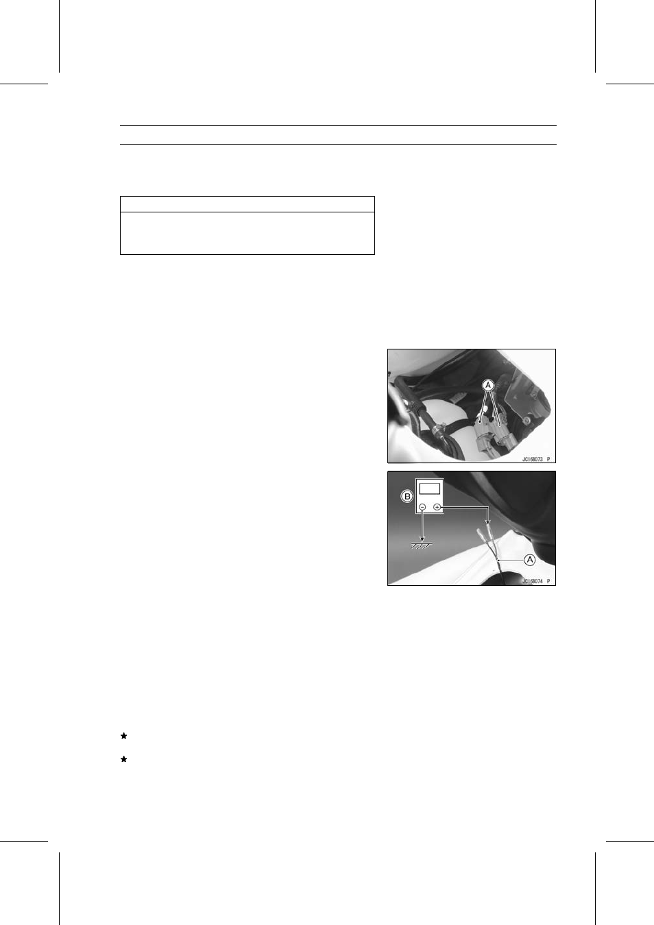
Disconnect the ignition coil primary lead connector(s) [A].
•
Connect the harness adapter [A] and a digital voltmeter
[B].
Special Tool - Harness Adapter: 57001-1562
•
Turn the ignition switch ON and push the lanyard key un-
der the stop button.
•
Pushing the start button, run the engine 5
∼
6 seconds at
idling to measure the input voltage.
○
Wait 15 seconds before using the starter again.
Ignition Coil Input Voltage at Ignition Coil
Connections for Ignition Coil #1, #4
Meter (+) → R/Y lead
Meter (–) → Battery (–) terminal
Connections for Ignition Coil #2, #3
Meter (+) → R/Y lead
Meter (–) → Battery (–) terminal
Input Voltage at ECU
Standard:
Battery Voltage
If the reading is out of the standard, check the wiring (see
next wiring diagram).
If the reading is good, the input voltage is normal. Crank
the engine, and check the peak voltage of the ignition
coils (see Electrical System chapter) in order to check the
primary coils.