Test run, Vi-5 – Sanyo KHH2672R / CH2672R User Manual
Page 175
VI-5
SM831148
1
2
3
4
5
6
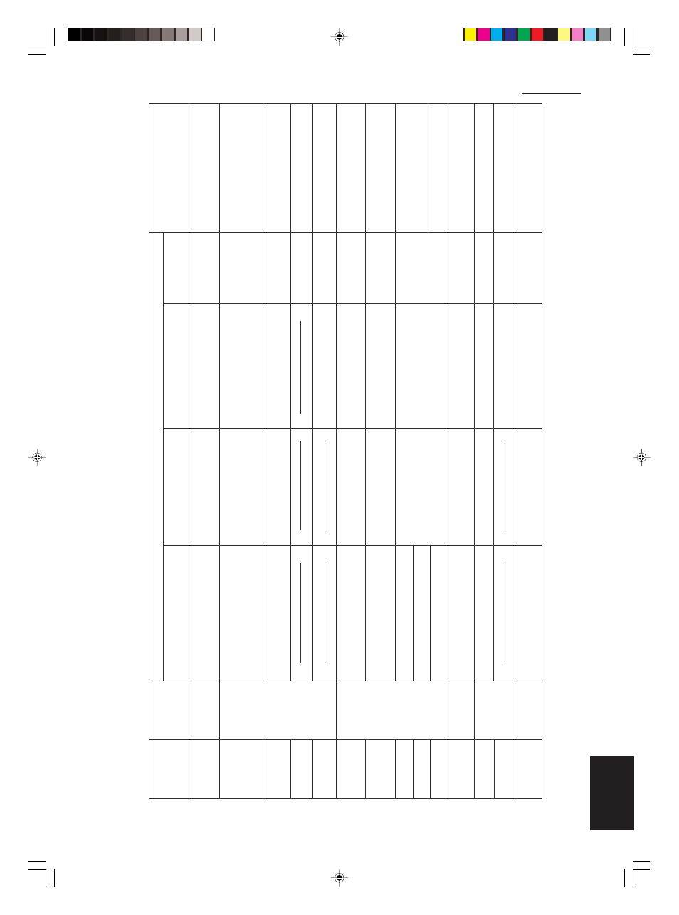
6. Test run
Wired remote
contr
o
ller di
spla
y
Cause
Correction
Nothi
ng
is
di
spla
ye
d
Nothing is
di
spla
ye
d
E 0 1
dis
pla
ye
d
E 0 2
di
spla
ye
d
E 0 9
di
spla
ye
d
E 1 4
displa
ye
d
E 0 4
displa
ye
d
E 0 6
di
spla
ye
d
E 1 5
displa
ye
d
E 1 6
displa
ye
d
E 2 0
di
spla
ye
d
P 0 5
di
spla
ye
d
L 0 2
displa
ye
d
L 1 3
displa
ye
d
P 0 9
displa
ye
d
L 0 7
displa
ye
d
Indoor unit
receiver lamp
Oper
ating
lamp
is b
linking.
Standb
y lamp
is
bl
in
king.
Both the Oper
ation
lamp and
S
tan
db
y
lamp are b
linking
together
.
Oper
atio
n
lamp an
d
S
tan
db
y lamp are
b
linking alter
nately
.
Timer lamp a
nd
S
tan
db
y lamp are
b
linking alter
nately
.
●
Remote co
n
troller is
not connected correctly
.
●
In
door
un
it po
w
er i
s
n
ot ON.
●
A
utomatic addre
ss
setti
ng has
n
ot been
completed.
●
Inter-unit control wir
ing is cut or is
not
connected correctly
.
●
Remote controller is
n
ot conn
ected correctly
(remote controller receiving f
ailure).
●
Remote co
ntroller is
not connected correctly
(f
ailure in tr
ansmission from remote controller
to indoor
unit).
●
Indoor-outdoor inter-unit wir
ing is
n
ot
connected correctly
.
●
Indoor
unit capacity is too lo
w
.
●
Indoor
un
it capacity i
s too hi
g
h.
●
No
s
er
ial
s
ign
al i
s
bei
ng
receiv
ed at all from
the indoor
units
.
●
Inter-unit circu
it or ope
n pha
s
e i
n
the o
u
tdoor
unit po
w
e
r
●
Insu
fficie
nt
g
as
●
Indoor-outdoor
unit type mismatch
●
The indoor
unit ceiling panel connector is
not
co
nn
ected correctly
.
●
Remote controller is
not co
nn
ected with
indoor
unit correctly
●
Indoor
unit po
w
er is
not ON.
●
A
utomatic address
s
etting has
not been
completed.
●
Inter-unit control wir
ing is cut or is
not
connected correctly
.
●
Remote co
n
troller is
not connected with
indoor
unit correctly
●
Remote controller is
not connected with
indoor
unit correctly
●
Same as at left
●
Indoor-outdoor inter-un
it wir
ing is cut or
is
not connected correctly
.
●
Same a
s
at left
●
Re
ve
rsed phase or open phase in the
3
-pha
s
e po
w
er at on
e of the o
utdoor
un
its
i
n the
gr
o
u
p
●
Same as at left
●
Same as at left
●
Same as at left
●
Same as at left
●
Same as at left
●
Same as at left
●
Same as at left
●
Same as at left
●
Same as at left
●
Same as at left
●
Same a
s at left
●
Same as at left
●
Same as
at left
●
S
ame as at left
●
Same as at left
●
Same as at left
●
Same as at left
●
Same a
s
at left
●
Remote controller crosso
ver wir
ing is cut or
is
not connected correctly
.
●
Indoor
unit ceiling panel connector is
not
connected correctly
.
●
Remote controller crosso
ver wir
ing is co
nn
ected
to the indoor
unit, ho
w
ev
er it is
set f
or individual
oper
atio
n.
Connect the remote controller correctly
.
Tu
rn
ON the indoor
unit po
w
e
r.
●
2 remote controllers are
set as the main remote
controller
.
Chec
k the remote controller and inter-unit
control wir
ing.
P
e
rf
or
m automatic address
setting.
Connect the remote controller correctly
.
Ref
er to 11-8-6 Main-sub remote control, and
mak
e the correct settings
.
Chec
k
the remote controller crosso
ver wir
ing.
P
e
rf
or
m automatic address
setting again.
Connect the wir
ing correctly
.
Ref
er to 11-8
S
ystem Control, and mak
e
the
correct
settings
.
Chec
k
that the total capacitie
s
of the i
n
door
and outdoor
un
it
s are appropr
iate
.
Chec
k that the indoor
unit po
w
er is ON, and that
the inter-unit control wir
ing is connected correctly
.
Re
ve
rse 2 phases of the outdoor
unit
3-phase
po
w
er and connect them correctly
.
Chec
k
that the in
door a
nd o
u
tdoor
unit type
s
are correct.
P
e
rf
or
m a
utomatic address
s
etti
ng.
Connect the indoor
unit ceiling panel
co
nn
ector correctly
.
●
Ceiling panel connector at one of the
indoor
unit
s in the g
ro
u
p i
s
not
connected correctly
.
●
Re
ve
rsed phas
e or ope
n
pha
se in the
outdoor
unit
3-phase po
w
e
r
1:1 connectio
n
(sing
or
G
)
e
p
yt
el
u
p connection
Sim
ultaneous-oper
ation m
u
lti
system
(fle
x
ib
le combination)
Control b
y
main-sub
remote controllers
6-7.
T
a
b
le of Self-Dia
gnostic Functions and Corrections (X,
T
,
U
, K
T
ype)
6-7. T
able of Self-Diagnostic Functions and Corrections (X, T
, U, K T
ype)