Interlock and auto bypass on vfd fault, Description, Settings – Siemens SED2 VFD Electronic Bypass Option 125-3208 User Manual
Page 56
SED2 VFD Electronic Bypass Option Operating Instructions
48
Siemens Building Technologies, Inc.
Interlock and Auto Bypass on VFD Fault
Description
Interlock and Auto Bypass features are both active. Auto bypass now becomes auto
bypass on a VFD fault only (bypass is initiated by the SED2 Fault and this digital
output must always be programmed to VFD fault).
• All set-up is the same as with Interlock (see the Interlock section in
Application Feature Setup).
• Hand bypass is now initiated by SED2 Fault.
• The Programmable Output is still used to initiate the proofing sequence.
Settings
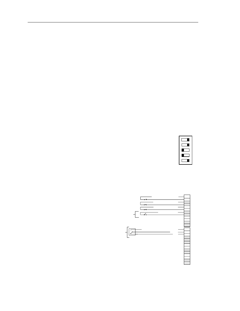
Interlock and Auto Bypass requires that Controller
board DIP Switches 2 and 3 are set ON.
NOTE:
During operation, the Auto Bypass Enabled
indicator is on steady. Also, the Interlock
Start Logic Enabled indicator is on steady.
ON
12
5
34
12
5
34
ON
OFF
SW1
VFD0120R1
See the Auto Bypass without Interlock on VFD Relay Output and Interlock sections
for parameter settings.
Wiring Example for
Interlock and Auto
Bypass on VFD Fault
Customer
Proof
Power to
Customer
Device
Programmable Output, NO
COM
NC
DIGITAL OUTPUTS
DIGITAL INPUTS
J2
J1
13
14
15
16
17
18
19
20
21
22
23
24
25
26
1
2
3
4
5
6
7
8
9
10
11
12
Remote Start Input
Remote Safety #1
Remote Safety #2
Interlock Start
VFD0115R2