Electronic bypass option overview, General description – Siemens SED2 VFD Electronic Bypass Option 125-3208 User Manual
Page 12
SED2 VFD Electronic Bypass Option Operating Instructions
4
Siemens Building Technologies, Inc.
Electronic Bypass Option Overview
General Description
During normal operation in a typical
application, the input and output
contactors close and the SED2
operates the motor (Figure 1). The
bypass contactor provides the ability to
operate the motor on utility power and
eliminate the SED2 from the motor
control circuit. The SED2 Electronic
Bypass Option also allows you to select
features that enhance the control of the
contactors and the outputs that report
operation.
BYPASS
CONTACTOR
INPUT
CONTACTOR
OUTPUT
CONTACTOR
MOTOR
VFD
OVERLOAD
RELAY
VFD0093R1
Figure 1. Functional Block Diagram of
Typical Electronic Bypass Option.
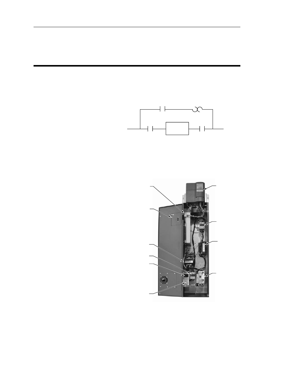
The SED2 Electronic Bypass
(E-Bypass) Option consists of a SED2
VFD, and a bypass enclosure with
electronic controls (Figure 2). The
electronic controls include:
• Controller
board
• Keypad
• Step-down power transformer
• Contactors:
− Bypass
− Output
− Input
(optional)
• Overload
(current)
relay
• Reactor
(optional)
• Disconnect switch (or optional
circuit breaker)
• Fuses
(optional)
• Cable
harnesses
REACTOR
(OPTIONAL)
INPUT
CONTACTOR
STEP-DOWN
POWER
TRANSFORMER
CONTROLLER
BOARD
KEYPAD
(DOOR
MOUNTED)
OUTPUT
CONTACTOR
BYPASS
CONTACTOR
DISCONNECT
SWITCH
(OR OPTIONAL
CIRCUIT BREAKER
SHOWN)
SED2 VFD
OVERLOAD
(CURRENT)
RELAY
VFD0094R1
Figure 2. Typical SED2 E-Bypass Components.