Connecting to computer devices, Connecting to devices which control the projector, Power – JVC DLA-G150CLE User Manual
Page 55
DLA-G150CLU
DLA-G150CLE
1-55
No.51931
28
Connecting to Various Devices
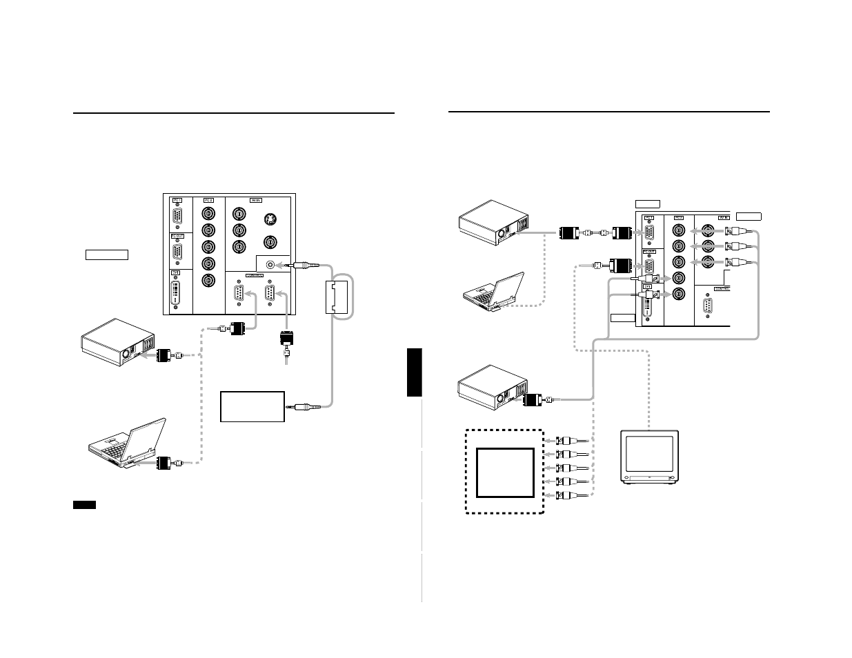
Connecting to Computer Devices
Before connection, be sure to turn off both the projector and computer devices.
• Read thoroughly the manual that comes with each device.
■
Connection to an IBM PC or IBM-compatible computer
• Use the supplied personal computer connection cable. Also, prepare cables required for connecting the devices
connected.
Y
P
B
/B-Y
P
R
/R-Y
IN
R
G
B
H
IN
V
POWER
• Desktop type
To PC 1
Personal Computer
connection cable (supplied)
To monitor
connector
To B
To R
To G
• Notebook type
* There are some notebook types which
do not allow the computer’s LCD to work
if an external display is connected. With
such a notebook computer, the LCD
display and external display output
need to be switched.
• RGB output devices
• Desktop type
To monitor connector
Separate cable (separately available)
To PC 2
To H/Cs
To V
Laser video disc
player, etc.
To G
To R
To H/Cs
To V
To PC 2
To PC 2
To PC 1
To PC OUT
Cable
supplied
with the
display (or
separately
available)
(D-sub 3-
row 15-pin)
* When a display monitor is connected to
the PC OUT terminal, you can view the
video from the computer on the monitor.
Display monitor
To B
27
Connecting to Various Devices
ENGLISH
DEUTSH
FRAN
ÇAIS
ITALIANO
ESPAÑOL
Connecting to Devices which Control the Projector
Before connection, be sure to turn off both the projector and devices to be connected.
• Read thoroughly the manual that comes with each device to be connected.
• By connecting a computer to the RS-232C terminal, you can control the projector. Also, you can make an infrared remote
sensor extension unit and connect it to the REMOTE terminal of the projector.
* Obtain connection cables as required. Use a reverse connection cable.
* For details, refer to “RS-232C external control” on page 74.
* For further details, consult your dealer or an authorized service center.
Note
• When connecting the cable to the REMOTE terminal, refer to “How to attach the ferrite core” on page 29.
Y
P
B
/B-Y
P
R
/R-Y
IN
REMOTE
Y/C
VIDEO
R
G
B
H
IN
OUT
V
• Desktop type
To RS-232C connector
To RS-232C connector
RS-232C reverse
connection cable
(separately available)
To RS-232C connector
• Note type
To
R
E
M
O
TE
t
er
m
in
a
l
TO CONTROL
Infrared remote sensor
extension unit
(Needs to be made)
* By directly connecting the OUT terminal
to the second DLA-G150CLE IN
terminal, a number of DLA-G150CLE
units can be controlled by a single
computer.
*