Names and functions of p a rt s, Installation method, Mini – JVC SA-DV6000 User Manual
Page 6: English, Br-d v6000, Front p anel rear p anel
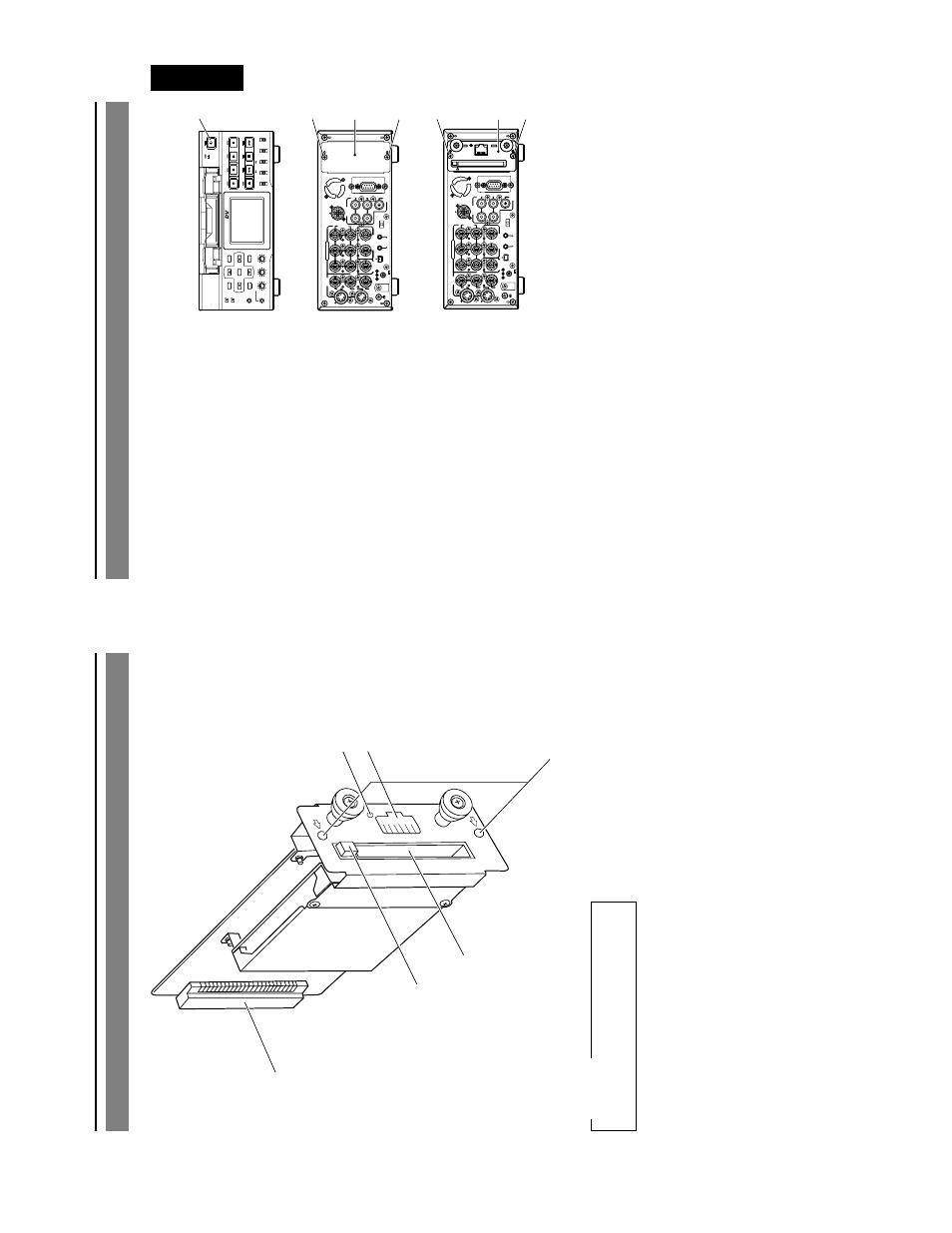
E-8
1
PC Car
d Slot
Inser
t LAN card, CompactFlash card, etc.
here
.
2
EJECT Button
Push to eject the card.
3
Mounting scre
w holes
Used to install this product to the rear
panel of the BR-D
V6000 with scre
ws
.
Names and Functions of P
a
rt
s
5
3
1
2
4
6
4
Connector
Connects b
y
pushing in the connector f
o
r
connecting to the
VCR main unit.
5
LAN Connector
Connect LAN cab
le here
.
6
LINK LED
Lights up when netw
or
k is connected.
Please don’t touch the metal par
ts other
than the panel.
CA
UTION
E-9
English
Installation Method
F
ollo
w the f
ollo
wing procedure to install this
product to the BR-D
V6000 D
V
Video Cassette
Recorder
.
1
Switch off the
VCR po
wer
.
2
Remo
v
e
the two scre
ws
2
from the co
v
e
r
of the optional board installation slot on
the f
ar r
ight side of the rear panel.
3
Remo
v
e
the co
v
er
3
.
4
Inser
t the board of this product (SA-
D
V6000) along the guide r
ails
, correctly
align the connectors and push in.
5
Fix the SA-D
V6000 onto the BR-D
V6000
main unit using the tw
o scre
ws
2
that
w
ere remo
v
ed in step
2
.
BR-D
V
6000
PROFESSIONAL
MENU
RESET
A.DUB
EJECT
COUNTER
AU
DIO
INPUT SELECT
MONIT
O
R
OUTPUT
REMO
T
E
LOCAL
CTL
L
MIX
R
CH-1/2
MIX
CH-3/4
DV
LINE
Y/C
(CPN)
TC
UB
REW
ST
OP
FF
REC
OPERA
TE
PLA
Y
P
A
USE
DISP
SET
SEARCH+
BLANK
CUE UP
HOLD
PHONES
REC LEVEL
CH-1/3
CH-2/4
MIC
SEARCH–
Mini
VIDEO
LINE
IN
OUT
MONIT
OR
OUT
DC12V
DV
IN/OUT
IN
OUT
OFF
AU
DIO
REMO
TE2
IN
B-Y
R-Y
SYNC IN
TIME CODE
IN
OUT
Y
COMPONENT
OUT
CH 1/3
C
H 2/4
IN
OUT
MONIT
OR
OUT
REMO
TE1
TIMER
REC
PLA
Y
SERIAL
REMO
TE
SIGNAL
GND
Y/C
VIDEO
LINE
IN
OUT
MONIT
O
R
OUT
DC12V
DV
IN/OUT
IN
OUT
OFF
A
UDIO
REMO
TE2
IN
B-Y
R-Y
SYNC IN
TIME CODE
IN
OUT
Y
COMPONENT
OUT
CH 1/3
CH 2/4
IN
OUT
MONIT
OR
OUT
REMO
TE1
TIMER
REC
PLA
Y
SERIAL
REMO
T
E
SIGNAL
GND
Y/C
LAN
2
3
5
5
4
1
2
BR-D
V6000
F
ront P
anel
Rear P
anel