Before using the dtr-10.5 —continued, Installing the option boards, Getting star ted – Integra DTR-10.5 User Manual
Page 11: Board surface
11
Before Using the DTR-10.5
—Continued
The option boards should be installed in their individual
designated slots. Installing the option board a different
slot may cause failure.
Installing the Option Boards
1
Turn off the power and unplug the power
cord both from the DTR-10.5 and electrical
outlet.
Be sure to turn off the power of the DTR-10.5.
Inserting or removing an option board with the
DTR-10.5 turned on may cause failure.
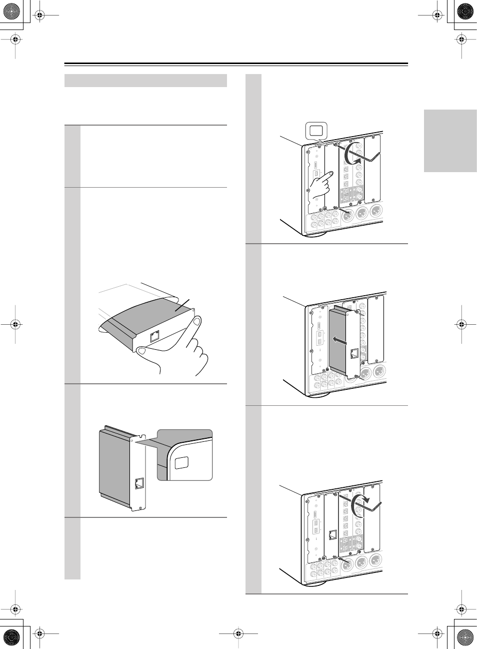
2
Take the option board out from the pack-
age carefully.
The option board incorporates many components,
terminals and connectors along with solderings
on its surface. Touching the board with your fin-
gers may cause failure or damage from static elec-
tricity, incorrect contact and so on. When
handling the board, be sure to hold the outer part
or panel section of the board without touching the
board surface.
3
Check the alphabet letter on the option
board.
The alphabet letter is printed at the top left corner
of the panel section.
4
Remove the sub-panel with the same
alphabet letter as your option board from
the back of the DTR-10.5.
Use the supplied Allen wrench to loosen the screw
gradually, while holding the sub-panel so that the
panel will not drop down.
“
Net
-Tune
”
is
a
tradem
ark
of
Onkyo
Corporation.
ETHERNET
(
Net
-Tune
)
B
Board
surface
“Net-Tun
e”
is a tradem
ark of
Onkyo
Corpo
ration.
ETHER
NET
(
Net-Tune
)
B
B
The sub-panels are fixed to the DTR-10.5 with
two screws at the top and bottom, while the panel
that covers slots [H] and [I] is fixed with four
screws at the top and bottom. Keep the removed
screws for fixing the option board.
5
Insert the option board along the rail
softly. When the board comes to the posi-
tion where it stops but does not cover the
slot completely, push the board forward a
little bit more strongly.
6
Fix the option board firmly to the DTR-10.5
using the removed screws.
Be sure to tighten the screws firmly to the
DTR-10.5. If the screws are loose, contact failures
for ground or signal wires may occur at the section
between the DTR-10.5’s slot terminal and the
option board, which may cause the DTR-10.5 or
board to fail.
L
R
L
R
FRON
T
CENTER
SURR
SURR
BACK
SUB
WOOF
ER
SURR
BACK
R
SURR
R
SUBW
OOFE
R
(
ASSIG
NABLE
)
(
SINGLE
)
(
ASSIG
NABLE
)
AUDIO
The i.L
INK log
o is a
tradem
arks of
Sony
Corpor
ation, r
egister
ed
in the
U.S. an
d othe
r
countr
ies.
S400
2
2
1
1
6
6
5
5
4
4
3
3
2
2
1
1
C
D
DIGITAL IN
DIGITA
L IN
OPTIC
AL
COAXIA
L
OUT
E
A
B
PRE O
UT A
B
L
R
L
R
FRON
T
CENTER
SURR
SURR
BACK
SUB
WOOF
ER
SURR
BACK
R
SURR
R
SUBW
OOFE
R
(
ASSIG
NABLE
)
(
SINGLE
)
(
ASSIG
NABLE
)
AUDIO
The i.L
INK log
o is a
tradem
arks of
Sony
Corpor
ation, r
egister
ed
in the
U.S. an
d othe
r
countr
ies.
S400
2
2
1
1
6
6
5
5
4
4
3
3
2
2
1
1
C
D
DIGITA
L IN
DIGITAL IN
OPTIC
AL
COAXIA
L
OUT
E
A
PRE O
UT A
“Net-T
une”
is a tra
demark
of
Onkyo
Corpo
ration.
ETHERNET
(
Net-Tu
ne)
B
L
R
L
R
FRON
T
CENTER
SURR
SURR
BACK
SUB
WOOF
ER
SURR
BACK
R
SURR
R
SUBW
OOFE
R
(
ASSIG
NABLE
)
(
SINGLE
)
(
ASSIG
NABLE
)
“Net-T
une”
is a tra
demark
of
Onkyo
Corpo
ration.
ETHERNET
(
Net-Tu
ne)
AUDIO
The i.L
INK log
o is a
tradem
arks of
Sony
Corpor
ation, r
egister
ed
in the
U.S. an
d othe
r
countr
ies.
S400
2
2
1
1
6
6
5
5
4
4
3
3
2
2
1
1
C
D
DIGITAL IN
DIGITA
L IN
OPTIC
AL
COAXIA
L
OUT
E
A
B
PRE O
UT A
Getting Star
ted