Intel SR1450 User Manual
Page 45
Hardware Installations and Upgrades
Intel
®
Server Chassis SR1450 User Guide
45
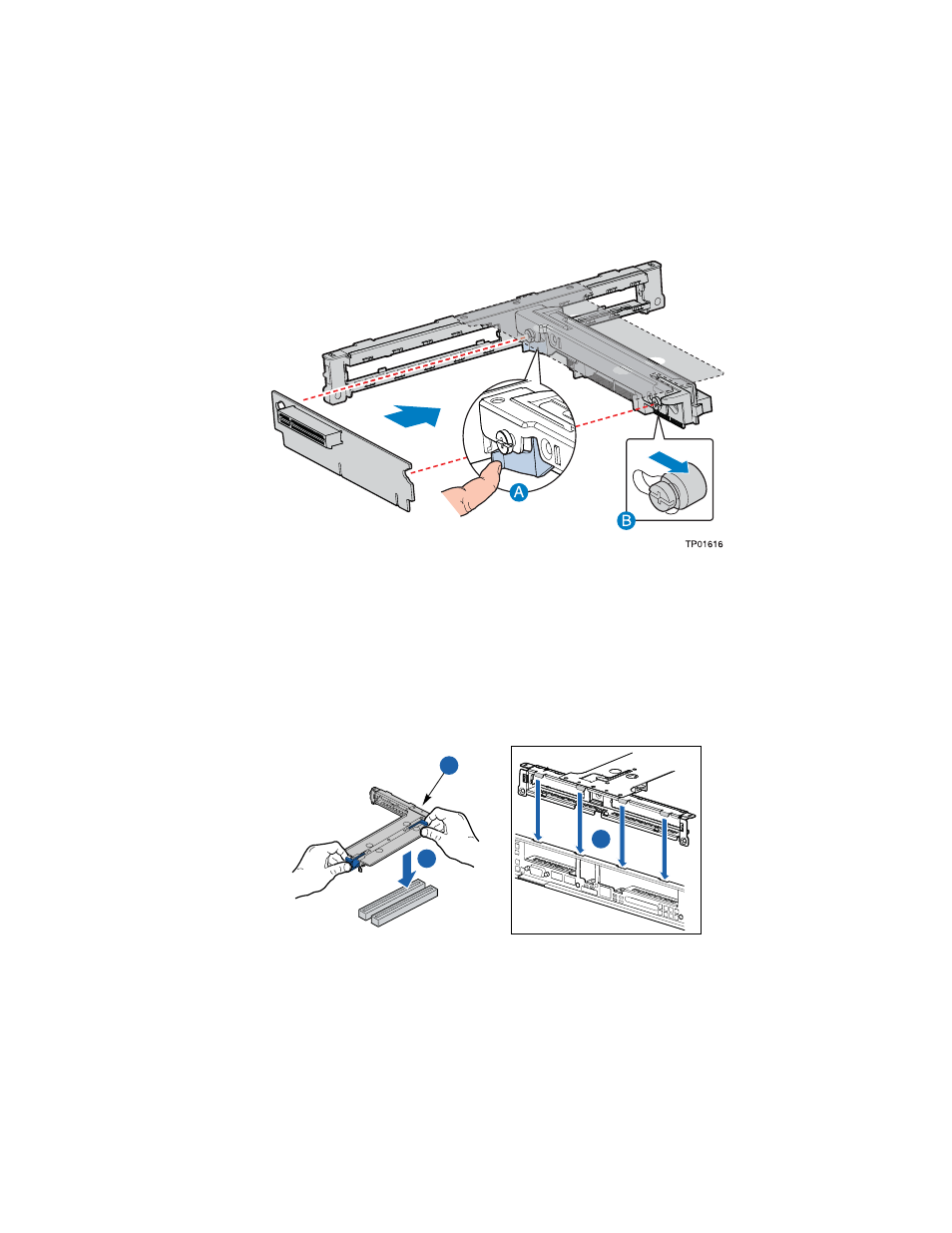
6. Line up the stand-offs on the riser assembly with the slot and the large hole on the riser card.
7. Press and hold the blue riser locking lever. See letter “A” in the figure below.
8. Place riser card onto the stand-offs. See letter “B” in the figure below.
9. Slide the riser card to the right to lock it into place.
10. Release the blue locking lever.
Figure 32. Installing an Add-in Card into the PCI Riser Assembly
11. Install a PCI add-in card, if desired. For instructions, see
“Installing a PCI Add-in Card.”
12. Position the riser assembly over the PCI sockets on the server board (see letter “A” in the figure
below), lining up the four hooks at the rear of the riser assembly with the four slots in the rear
of the chassis (see letter “B”).
13. Push the riser assembly down until the assembly is securely seated.
TP01618
A
B
B
Figure 33. Installing the PCI Riser Assembly into the Chassis
14. Install the chassis cover. For instructions, see
“Installing the Chassis Cover.”
15. Plug all peripheral devices and the AC power cable(s) back into the server.