Intel, Table 7, After – Intel IXDP465 User Manual
Page 19
Quick Start Guide—Intel
®
IXDP465 Development Platform
AN
Intel
®
IXDP465 Development Platform
May 2005
Order Number: 305825, Revision: 002
19
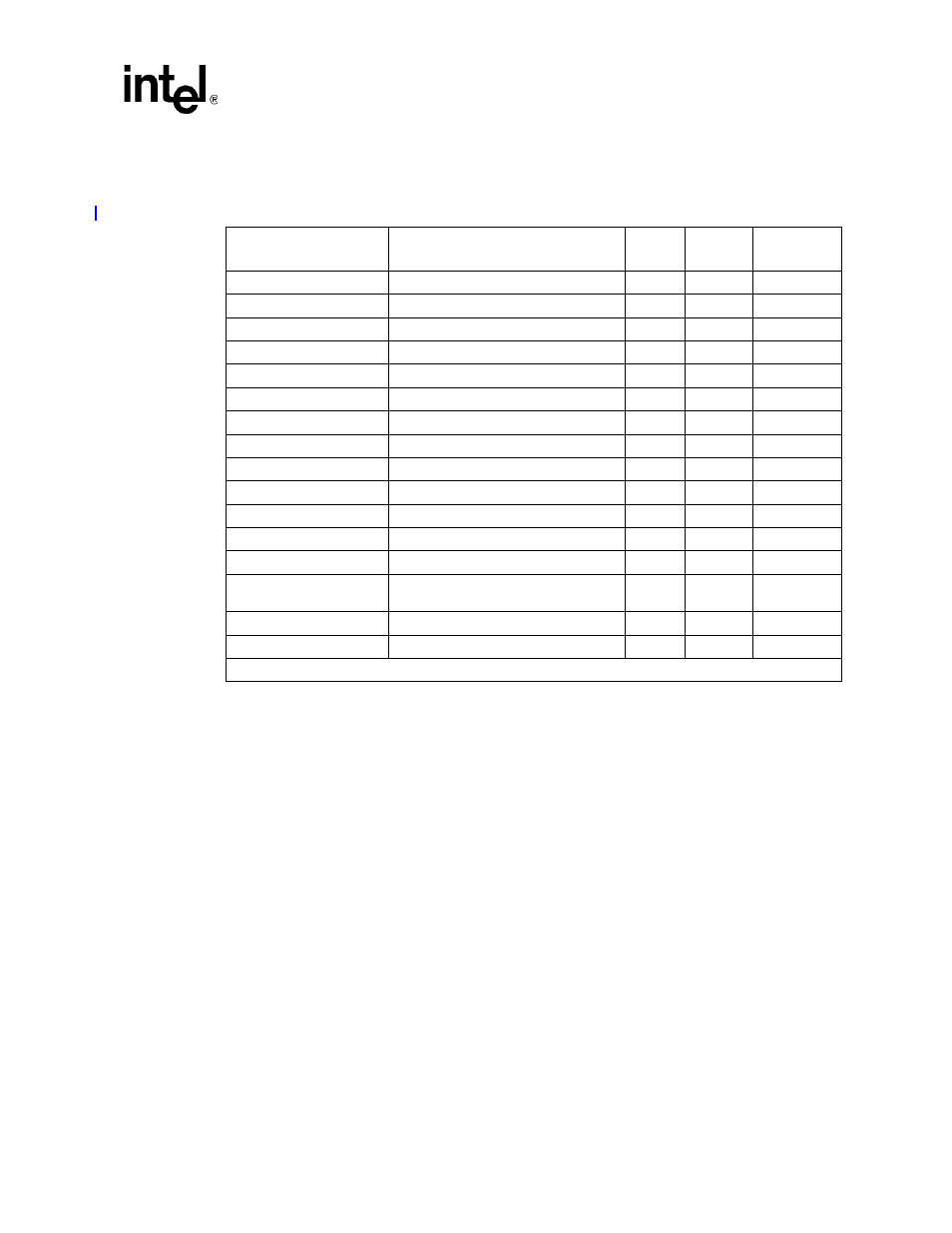
shows the exact locations for all LEDs on the IXDP465 development platform,
per the descriptions and colors summarized in
.
Table 7.
Intel
®
IXDP465 Development Platform LED Descriptions and Default Settings
Board Location
LED Indication when ON
Color
Default
Settings
Quick Start
Check
Power LED: +12V
+12V power is on
Green
ON
F
Power LED: +5V
+5V power is on
Green
ON
F
Power LED: -12V
-12V power is on
Green
ON
F
Power LED: +3.3V
+3.3V power is on
Green
ON
F
Power LED: +1.5V
+1.3V/+1.4V power is on
Green
ON
F
PCI LED: Option
PCI operating as option
Green
OFF
F
PCI LED: 66 MHz
PCI operating at 66 MHz
Green
ON
F
PCI LED: 33 MHz
PCI operating at 33 MHz
Green
OFF
F
PCI LED: Host
PCI operating as host
Green
ON
F
CPU Power LED: Reset
IXP465 system is in reset
Green
OFF
F
CPU Power LED: 3.3V
+3.3V power is applied to IXP465
Green
ON
F
CPU Power LED: 2.5V
+2.5V power is applied to IXP465
Green
ON
F
CPU Power LED: COREV
+1.3V/+1.4V power is applied to IXP465
Green
ON
F
GPIO LEDs:
GPIO 0 - GPIO 15
GPIO[15:0] driven low
Green
ON
F
GPIO LEDs: Power LED
+2.5V power is on
Green
ON
F
FLASH STATUS
Flash device is being programmed
Yellow
OFF
F
†
Board silkscreen text reads “+1.5V” however, core voltage is actually 1.3/1.4V.