0 lcd display and led indicators, Lcd display and led indicators, Intel – Intel IXDP465 User Manual
Page 18: Section 8.0, Figure 5, Ee figure 5)
Intel
®
IXDP465 Development Platform—Quick Start Guide
May 2005
Intel
®
IXDP465 Development Platform
AN
18
Order Number: 305825, Revision: 002
8.0
LCD Display and LED Indicators
This section provides an overview of the LCD display, and also defines the locations, colors, and
definitions of all LEDs, so that they can be visually monitored for proper power-up and booting.
The IXDP465 development platform provides a 2 x16-digit LCD display that can be used for
software debug. The IXP465 Expansion Data Bus directly drives this display. When booting the
factory-installed boot images for either Wind River* VxWorks* or RedHat* RedBoot*, this LCD
display can be monitored for visual indication of a successful boot, as described in
this guide.
The IXDP465 development platform also uses many LEDs scattered throughout the different board
assemblies, each of which provides a different visual indication of status, as summarized in
. After powering up the platform for the first time, all of the default settings must be
checked to ensure correct operation.
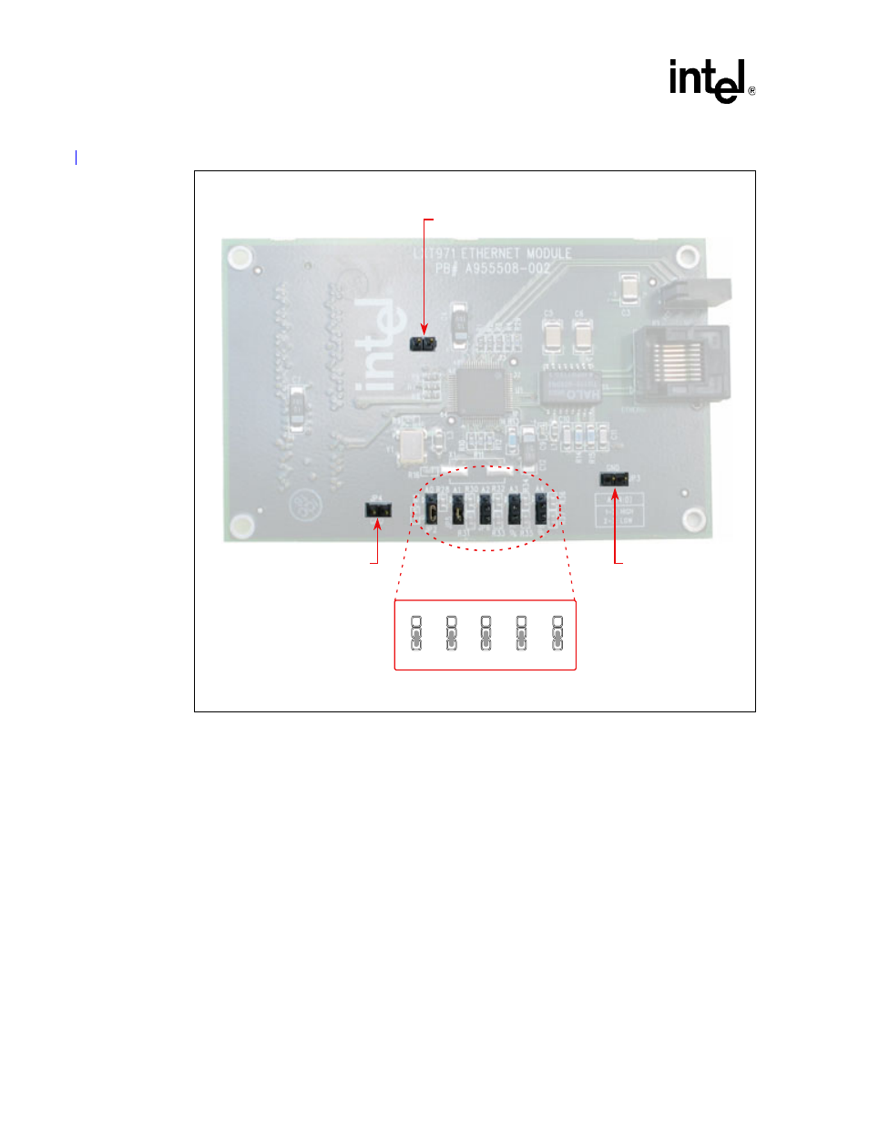
Figure 5.
Intel
®
IXPETM465 Ethernet PHY Mezzanine Card Jumper Locations
B5037-01
GND
JP1 (Not installed)
GND
JP3 (Not installed)
A0
JP2
A1
JP5
A2
JP6
A3
JP7
A4
JP8
GND
JP4 (Not installed)
ETHERNET
ADDRESS JUMPERS